
Page 384 - APPLIED PROCESS DESIGN FOR CHEMICAL AND PETROCHEMICAL PLANTS, Volume 1, 3rd Edition
P. 384
352 Applied Process Design for Chemical and Petrochemical Plants
MECHANICAL VACUUM PUMPS STEAM-JET EJECTORS
TEMPERATURE
BOILING POINT= 212°F
FOR WATER AT
NORMAL ATMOS. PRESS.
250 SINGLE STAGE OR
ROTARY Flt.lAL STAGE OF a: 150° F.
,C VANE AND MULTISTAGE UNITS 0
a.
>
(WATER SEALED)w UJ 4" ""
..J <.!)
(!) <I: a:
;z .... l&J
� � I00°F,
RECIPROCATIN: en 50 2" �
� TWO STAGE 0
(DRY VAC.PUMP)
l&J
25 1.0" .....
a:
O UJ ""
�� ::,
........
.....
en
0.4" "" 50° F.
UI
5 0.2"
FREEZING
0.1 11 POINT
ROTARY MICRONS
(OIL SEALED)
1mm. 1000 0°F.
FOUR STAGE
a::
DISCHARGE TO t 500 >
0
a.
""
l&J
. MUL,IST··· .,.� .O .I na, _._"- I O� O FIVE STAGE
ROTARY PUMP 250 o
� 50
i'.!
t DIFFUSION PUMPS z �� 25
1 I
(OIL 6 MERCURY)
-
VAPOR TYPES
in
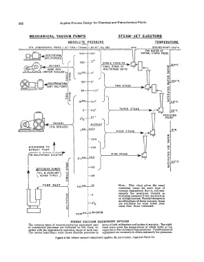
PUMP INLET O.Oll!!l! �� l � O Note: This chart gives the usual
operating range for each type of
vacuum equipment; that is, not nec-
essarily the maximum vacuum or
5 minimum pressure it can maintain in
an airtight system. Special designs or
modifications of these common types
2� are available for even lower pres-
2
sures than those indicated.
O.OOlmm. =IMICRON
WHERE VACUUM EQUIPMENT APPLIES
The common types of vacuum-producing equipment used terms of both millimeters and inches of mercury. The rlght-
in commercial processes are indicated on this chart, to- hand scale gives the temperatures at which water or ice
gether with the approximate operating range of each 011.e. vaporizes at the corresponding pressures. Combinations of
The central loqarilhmic scale shows absolute pressures in equipment are necessary to obtain extremely low pressures.
Figure 6·9A. Where vacuum equipment applies. By permission, Ingersoll-Rand Co.