
Page 415 - APPLIED PROCESS DESIGN FOR CHEMICAL AND PETROCHEMICAL PLANTS, Volume 1, 3rd Edition
P. 415
Ejectors and Mechanical Vacuum Systems 383
STEAM STEAM STEAM STEAM
NASH
SEPARATOR
RECYCLE
TOWER
TOW�R
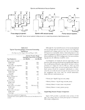
Three-stage jet ejector. Ejector with vacuum pump. Pump vacuum system.
Figuro 6-33. Typical vacuum systems holding vacuum on a vessel. By permission, Nash Engineering Co.
Table 6-17 Although the thermal efficiencies of various mechanical
Typical Operating Range of Vacuum Generating vacuum pumps and even steam jet ejectors vary with each
Equipment manufacturer's design and even size, the curves of Figure
(For Ejectors, See Figure 6-9A and Figure 6-25) 6-34 present a reasonable relative relationship between the
types of equipment. Steam jets shown are used for surface
Absolute Pressure Range intercondensers with 70°F cooling water. For non-condens-
(Discharge, then Lower or Suction) ing ejectors, the efficiency would be lower.
Type Equipment mm Hg Abs mm Hg Abs
--------·---·
Rotary piston (Liquid) Combinations of steam jet ejectors operating in con-
Single-stage 760 250 junction with mechanical pumps can significantly improve
Two-stage 250 150 the overall system efficiency, especially in the lower suction
Rotary Lobe, two impellers pressure torr range of l torr to l.00 torr. They can exist
Single-stage 760 250 beyond the range cited, but tend to fall off above 200 torr.
Two-stage 250 75 Each system should be examined individually to deter-
Helical rotary lobe mine the net result, because the specific manufacturer and
Single-stage 760 200 the equipment size enter into the overall assessment.
Two-st.age 200 75 Some effective combinations are:
Centrifugal 760 130
Rotary sliding vane
Single-stage 760 75 • Steam jet-liquid ring vacuum pump
Two-stage 75 10
Reciprocating • Rotary blower-liquid ring vacuum pump
Single-stage 760 30
Two-st.age 30 10 • Rotary blower-rotary vane compressor
Rotary piston, oil sealed Microns, Abs
Single-stage 760 60 • Rotary blower-rotary piston pump
Two-stage 60
Rotary vane, oil sealed
Single-stage 760 7 Liquid Ring Vacuum Pwnps/Compressor
Two-stage 7 0.08
"Varies with manufacturer's equipment. Figure 6-35 provides a pictorial cross section of this
Compiled from various published references and manufacturer's lit-
erature. type unit along with an actual photograph of disassem-
bled major components.