
Page 411 - APPLIED PROCESS DESIGN FOR CHEMICAL AND PETROCHEMICAL PLANTS, Volume 1, 3rd Edition
P. 411
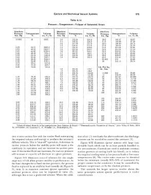
Ejectors and Mechanical Vacuum Systems                             379


                                                          Table 6-14
                                        Pressure-Temperature-Volume  of Saturated Steam


            Absolute                           Absolute                            Absolute
             Pressure   Temperature   Volume   Pressure   Temperature   Volume     Pressure   Temperature   Volume
             Ins. Hg      oF.      cu. ft./lb.   Ins. Hg      OF.      cu. ft./lb.   Ins.  Hg    OF.      cu. ft./lb.
                                                                                                        ------
              0.1803      32         3306         3.0       115.06      231.6       20.0       192.37      39.07
                                                  3.1       116.22      224.5       21.0       i94.68      37.32
                                                  3.2       117.35      217.9       22.0       196.90      35.73
                                                  3.3       118.44      211.8       23.0       199.03      34.28
              0.20        34.57      2996.0       3.4       119.51      205.9       24.0       201.09      32.94
              0.25        40.23      2423.7       3.5       120.56      200.3       25.0       203.08      31.70
              0.30        44.96      2039.4       3.6       121.57      195.1       26.0       205.00      30.56
              0.35        49.f)6     1761.0       3.7       122.57      190.1       27.0    i   206.87     29.50
              0.40        52.tH      1552.8       3.8       123.53      185.5       28.0       208.67      28.52
              0.45        55.89      1387.7       3.9       124.49      181.0       29.0       210.43      27.60
              0.50        58.80      1256.4                                         29.922     212         26.80
              0.60        63.96      1057. l                                         30        212.13      26.74
              0.70        68A.1       913.8
              0.80        72.32       805.7
              0.90        75.84       720.8                                      Lb.  Per Sq.
                                                  4.0       125.43      176.7      In.  Abs.
                                                  4.5       129.78      158.2
                                                  5.0       133.76      143.25       14.696    212         26.80
                                                  5.5       137.41      131.00       15        213.0:3     26.29
              1.00        79.03       652.3       6.0       140.78      120.72      20         227.96      20.089
              1.10        81.96       596.0       6.5       143.92      112.00      30         250.33      13.746
              1.20        84.64       549.5       7.0       146.86      104.46      40         267.25      10.498
              1.30   I    87.17       509.1       7.5       149.63       97.92      50         281.01   I   8.515
              1.40        89.51       474.9       8.0       152.24   I   92.16      60         292.71       7.175
              1.50        91.72       444.9       8.5       154.72       87.08      70         302.92       6.206
              1.60        93.81       418.5       9.0       157.09       82.52   i   80        312.03       5.472
              1.70        95.78       395.3       9.5       159.48       78.48      90         320.27       4.896
              1.80        97.65       374.7                                         100        327.81       4.432
              1.90        99.43       356.2
                                                                                    125        344.33       3.587
                                                                                    150        358.42   I   3.015
              2.00        101.14      339.2      10.0       161.49       74.76      175        370.75   !   2.602
              2.10        102.77      324.0      11.0       165.54       68.38      200        381.79       2.288
              2.20   I    104.33      310.3      12.0       169.28       63.03      225        391.79       2.0422
              2.30        105.85      297.4      13.0       172.78       58.47      250        400.95       1.8438
              2.40   !    107.30      285.8      14.0       176.05       54.55      275        409.43       1.6804
              2.50        108.71      274.9      15.0       179.14       51.14
              2.60        ll0.06      265.0      16.0       182.05       48.14
              2.70        111.37      255.7      17.0       184.82       45.48      300        417.33       1.5433
              2.80        112.63      247.2      18.0       187.45       43.11      350        431.72       1.3260
              2.90        113.86      239.1      19.0       189.96       40.99      400        444.59       1.1613
                     I                                                                                  I
               Values obtained directly or by interpolation from  Keenan & Keyes-"Thermodynamic  Properties of Steam," John  Wiley  &  Sons,  1936
           by  permission and Courtesy C. H. Wheeler Co.,  Philadelphia,  Pa.


           tion at zero suction flow with  the motive fluid maintaining   tion of air ( 1) overloads the aftercondenser,  the discharge
           the required volume and energy to produce the necessary   mixture can be recycled to control the pressure  [3].
           diffuser velocity.  This is "shut-off" operation. A decrease in   Figure  6-32  illustrates  ejector  systems  with  large  con-
           motive  pressure  below  the  stability  point will  cause  a  dis-   densable  loads which  can  be  at least partially  handled  in
           continuity  in  operation  and  an  increase  in  suction  pres-   the  precondenser,  Controls are used  to maintain constant
           sure. If  the motive fluid rate increases, the suction pressure   suction  pressure at varying loads  (air bleed), or to reduce
           will increase or capacity will decrease at a given pressure.   the required cooling water at low process loads or low water
             Figure  6-31  illustrates  control  schemes  for  the  single   temperatures  [2]. The cooler water must not be  throttled
           stage unit wl  ich allow greater stability in performance. As   below  the minimum  (usually  30%-50%  of maximum)  for
           the load changes for a fixed suction pressure,  the process   proper contact in  the  condenser.  It may  be  controlled by
           fluid is replaced by an artificial load  (usually air; Figure 6-   tailwater temperature, or by  the absolute pressure.
           31,  item  1)  to  maintain  constant ejector operation.  An   The  controls  for  larger  systems  involve  about  the
           artificial  pressure  drop  can  be  imposed  by  valve  (2),   same  principles  unless  special  performance  is  under
           although  this  is  not a  preferred scheme.  Wben  the addi-   consideration.