Page 416 - APPLIED PROCESS DESIGN FOR CHEMICAL AND PETROCHEMICAL PLANTS, Volume 1, 3rd Edition
P. 416

384                      Applied Process Design for Chemical and Petrochemical Plants

                                                               How it Works: Typical of This Class of Pump (By
                                                               permission of [27])
          0.60
                                                                 'The Nash vacuum pump or compressor has only one
         >  0.50                                               moving  part-a  balanced  rotor  that  runs  without  any
         o                                                     internal lubrication. Such simplicity is possible because all
         c
         "'
        �   0.40                                               functions  of mechanical  pistons  or vanes  are  performed
                                                               by a rotating band of liquid compressant.
         Q)
        §  0.30                                    '  I          While  power to  keep  it rotating  is  transmitted  by  the
         Q)
        s:                                        '  I         rotor,  this ring of liquid tends to center itself in the cylin-
        f-  0.20                               For one-stage   drical  body.  Rotor axis  is  offset from  body  axis.  As  the
                                               liquid-ring
                                                               schematic diagram in Figure  6-35  shows,  liquid  cornpres-
          0.10                                                 sant almost fills,  then partly empties each rotor chamber
                                         Multistage steam jet
                                                               during a single revolution. That sets up the piston action.
                                                               Stationary  cones  inside  the  rotor  have  closed  sections
                           Suction  pressure,  torr            between  ported openings  that separate gas inlet and dis-
                                                               charge flows.
         Figure 6-34.  Rough estimates of thermal efficiency of various vacu-
         um  producing  systems.  By  permission,  Ryans,  J.  L.  and  Croll,  S.,   A portion of the liquid compressant passes out with dis-
         Chem.  Eng., V. 88,  No. 25, 1981, p. 72 [22].        charged air or gas.  It is usually taken out of the stream by


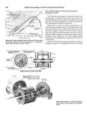
          O  IN  THIS secroa LIQUID MOVES
            OUTWARD -  DRAWS GAS  FROM
            INl.El PORlS INTO  ROTOR
            CHAM8EAS
                                                                        LIOUID


                             Nash vacuum pump schematic.


                                Disassembled view shows
                                appearance of rotor,  body
                                       and ported cones.


                                                                             Figure  6-35.  Diagram  of  liquid  ring  vacuum
                                                                             pump features.  By  permission,  Nash  Engineer-
                                                                             ing Co.
   411   412   413   414   415   416   417   418   419   420   421