
Page 414 - APPLIED PROCESS DESIGN FOR CHEMICAL AND PETROCHEMICAL PLANTS, Volume 1, 3rd Edition
P. 414
382 Applied Process Design for Chemical and Petrochemical Plants
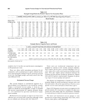
Table 6-15
Example Using Penberthy Model U Ejector for Evacuation Time
U MODEL EVACUATION TIME (in minutes per 100 cu ft at 100 PSIG Operating Steam Pressure)
Model Number
Suction Press
In. Hg abs. (hs) U-lH U-2H U-3H U-4H U-5H U-6H U-7H U-8H U-9H U-lOH U-llH U-12H U-13H U-14H U-15H U-16H
12" 4.68 3.08 1.98 1.37 1.01 .769 .610 .494 .409 .343 .293 .253 .206 .171 .145 .123
11" 5.06 3.32 2.14 1.48 1.09 .830 .657 .532 .441 .370 .316 .273 .222 .185 .156 .133
10" 5.44 3.57 2.30 1.59 1.17 .894 .707 .572 .474 .398 .340 .293 .239 .198 .168 .143
9" 5.85 3.84 2.46 1.71 1.26 .960 .760 .615 .510 .427 .365 .315 .257 .213 .180 .151
8" 6.29 4.14 2.66 1.84 1.35 1.04 .818 .662 .549 .460 .393 .339 .276 .230 .194 .165
7" 6.76 4.45 2.86 1.98 1.46 1.12 .880 .771 .590 .495 .423 .365 .297 .247 .209 .178
6" 7.35 4.84 3.10 2.15 1.58 1.21 .955 .774 .640 .537 .460 .396 .323 .268 .227 .193
5" 8.10 5.33 3.42 2.37 l.74 1.33 1.06 .853 .706 .592 .507 .437 .356 .295 .250 .213
4" 9.32 6.13 3.94 2.73 2.01 1.54 1.22 .981 .813 .683 .584 .504 .410 .340 .288 .245
3" 11.6 7.60 4.87 3.38 2.48 1.90 1.50 1.22 1.01 .845 .721 .623 .507 .422 .356 .304
By permission, Penberthy Inc.
Table 6-16
Example Ejector Capacity Factor and Steam
U AND L CAPACITY FACTOR AND STEAM CONSUMPTION
MODEL L-11-1 L-2H L-3H L-4H Ir51-I L-61-1 L-71-1 L-81-1 L-9I-I L-lOH L-llH L-12H L-131-1 Irl4H L-151-1 L-161-1
NUMBER U-1!-1 U-21-1 U-3I-l U-4I-I U-5H U-6H U-7H U-8H U-9H U-lOH U-1 lI-I U-121-1 U-13H U-14H U-15H U-16I-I
CAPACITY
FACTOR OPER- .293 .445 .694 1.00 1.36 1.78 2.25 2.78 3.36 4.0 4.69 5.4.3 6.66 8.03 9.49 11.12
ATING STEAM
CONSUMPTION 85 125 195 270 370 ·180 610 755 910 1090 1280 1480 1820 2190 2580 3030
LB. PER HOUR
(Qm) (Valid at standard nozzle pressure of 80, 100, 120, 140, 160, 180 or 200 PSlG.)
By permission, Penberthy Inc.
would be the U-3 in this case and its steam consumption These units are mechanical compressors but are
is 195 pounds per hour. designed to operate at low suction pressures absolute.
They require special seals to prevent inleakage of air or
There are often useful operations performed by jet
equipment, such as pumping air or gases, exhausting sys- other vapors that could create suction performance prob-
tems, heating liquids, mixing of liquids, priming (removal lems. They also require special clearances between the
of air) for centrifugal pumps, and many others (See Fig- housing and the pressure producing elemenr(s). Figures
ures 6-9B and 6-10). 6-9A and 6-10 present representative diagrams of operat-
ing ranges of vacuum pumps and ejectors.
Mechanical Vacuum Pumps The chapter on Compression in Volume 3 of this series
presents details of several mechanical vacuum units, and
The process designer or mechanical engineer in a this information will not be repeated here. However, more
process plant is not expected to, nor should he, actually specific vacuum units and system related data is given.
design a mechanical vacuum pump or steam jet, but
rather he should be knowledgeable enough to establish Figure 6-33 diagrams vacuum system arrangements for
the process requirements for capacity, pressure drops, process systems. It is important to examine the plant eco-
etc., and understand the operation and details of equip- nomics for each system plus the performance reliability
ment available. for maintaining the desired vacuum for process control.
Mechanical vacuum pumps are eight to ten times more The most used mechanical vacuum pumps or com-
efficient users of energy than steam jets; although, steam pressors are reciprocating, liquid-ring, rotary-vane, rotary
jets are reliable and cost less [23]. See Table 6-17. blower, rotary piston, and diaphragm.