Page 412 - APPLIED PROCESS DESIGN FOR CHEMICAL AND PETROCHEMICAL PLANTS, Volume 1, 3rd Edition
P. 412

380                       Applied Process Design for Chemical  and Petrochemical  Plants

                             Absolute  Pressure                   where  Pct  =  piston displacement cu fl/min
                                Controller
                                  0                                      V  = system volume, cu ft
                                                                         t  =  evacuation time, min
                                             Steam                      P 2  = absolute discharge pressure of pump, psia
                                                                        Pc  = absolute intake pressure of pump with closed intake
                                                                        P  1  = absolute intake pressure of pump
                           Process
                            §�
                                                                     The  relation  above  is  theoretical,  and  does  not  take
                                        Discharge                  into  account any  inleakage  while  pumping.  It is  recom-
                                                                   mended that a liberal multiplier of perhaps 2 or 3 be used
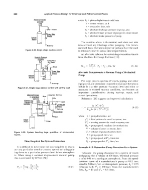
                      Figure 6-30.  Single-stage ejector control.   to estimate closer to actual  time requirements.
                                                                     An alternate relation for calculating evacuation time is
                                                                   from the Heat Exchange Institute  [11]:


                                                                                                               (6- 25)
                                             Steam
                                                                   Alternate Pumpdown to a Vacuum Using a Mechanical
                         Process                                   Pwnp
                         §_ystem
                                                                     For large  process  systems  of vessels,  piping,  and other
                                            Discharge              equipment,  the downtime required to evacuate the system
                                                                   before  it is  at  the  pressure  (vacuum)  level  and  then  to
                Figure 6-31. Single-stage ejector control with varying load.
                                                                   maintain  its  desired  vacuum  condition,  can  become  an
                                                                   important  consideration  during  start-up,  repair,  and
                        Absolute  Pressure   'Atmospheric  Air Bleed   restart operations.
                          or  Tem�eroture   Waler   I
                             Controller   I                          Reference  [26]  suggests an improved calculation:
                     Absolute  O         I
                      Pressure    -- -    --'----Steam
                     Controller   �----Pressure--   Low  Vacuum
                                i  -
                                ;                si�                                                            (6- 26)
                               -,--              Discharge
                               cJndenser
                                i
                                                                   where   t, = pumpdown time,  sec
                                                                          0
                     Process                                            p" = final pressure in vessel or system,  torr
                     §.rstem           Toil pipe
                                                                        P" 0  =  starting pressure in vessel or system,  torr
                                                                        Rps= pump speed,  rotations  (or strokes)/sec
                                                                         V' = volume of vessel or system,  liters
             Figure  6-32.  System  handling  large  quantities  of  condensable   V'  0  = volume of pump chamber,  liters
             vapors.                                                      S  =  pump speed, liters/sec
                                                                         S 0  =  pump speed, at P" liters/sec
                                                                                            0,
                     Time Required For System Evacuation                 Sn= pump speed at P" liters/sec
                                                                                           0,
                It is difficult to determine the time required  to evacu-   Example 6-13:  Determine Pump Downtime for a System
             ate  any particular vessel  or process  system including pip-
             ing down  to a particular pressure level  below atmospher-   Calculate  the pump downtime for a  system  of vessels
             ic.  When  using  a  constant  displacement vacuum  pump   and piping with a volume of 500 liters.  The final pressure
             this is estimated by O'Neil  [31]:                    is to be 0.01  torr,  starting at atmospheric. From the speed-
                                                                   pressure  curve  of a  manufacturer's  pump  at  0.01  torr,
                                                                                                              0
                    v      p  - p  c                               speed is 2.0 liters/sec. At atmospheric pressure, S =  2.75
                            2
                Pd= -log                                  (6-24)   liters/sec  with  P" 0   =  760  torr.  From  the  manufacturer's
                     t   c  p  - p
                            I   c                                  data,  Rps  =  15 and V' 0   =  0.5 liters.
   407   408   409   410   411   412   413   414   415   416   417