
Page 455 - APPLIED PROCESS DESIGN FOR CHEMICAL AND PETROCHEMICAL PLANTS, Volume 1, 3rd Edition
P. 455
Process Safety and Pressure-Relieving Devices 421
Figure 7-9E. Continued.
To meet code requirements, the relieving device must
be directly open to the system to be relieved, see Figures 7-
10, 7-11, and 7-12. For Figures 7,10, 7-11, and 7-12, the rup-
ture disk and the relief valve must be designed to handle
the relieving capacity at the relieving temperature without
allowing more than a 10% pressure build-up above the
maximum allowable working pressure of the unfired pres-
sure vessel ( or corresponding overpressure for other code
requirements). Figure 7-11 requires that the rupture disk
be designed the same as for Figure 7-10, 7-13A and 7-13B;
and Figure 7-12 requires that the relief valve be the prima-
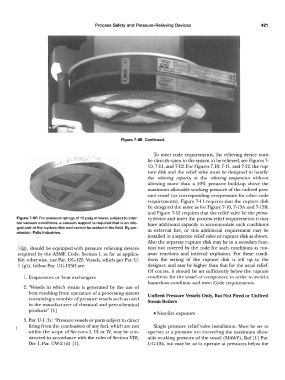
Figure 7-9F. For pressure ratings of 15 psig or lower, subject to inter- ry device and meet the process relief requirements; it may
nal vacuum conditions, a vacuum support is required that is an inte- have additional capacity to accommodate such conditions
gral part of the rupture disk and cannot be added in the field. By per- as external fire, or this additional requirement may be
mission, Falls Industries.
installed in a separate relief valve or rupture disk as shown.
Also the separate rupture disk may be in a secondary func-
1 ('g), should be equipped with pressure relieving devices tion not covered by the code for such conditions as run-
required by the ASME Code, Section I, as far as applica- away reactions and internal explosion. For these condi-
ble; otherwise, use Par. UG-125. Vessels, which per Par. U- tions the setting of the rupture disk is left up to the
1 (g)), follow Par. UG-125ffare: designer, and may be higher than that for the usual relief.
Of course, it should be set sufficiently below the rupture
1. Evaporators or heat exchangers condition for the vessel or component in order to avoid a
hazardous condition and meet Code requirements.
2. ''Vessels in which steam is generated by the use of
heat resulting from operation of a processing system Unfired Pressure Vessels Only, But Not Fired or Unfired
containing a number of pressure vessels such as used Steam Boilers
in the manufacturer of chemical and petrochemical
products" [l]
• Non-fire exposure
3. Par. U-1 (h) "Pressure vessels or parts subject to direct
firing from the combustion of any fuel, which are not Single pressure relief valve installation. Must be set to
within the scope of Sections I, III or IV, may be con- operate at a pressure not exceeding the maximum allow-
structed in accordance with the rules of Section VIII, able working pressure of the vessel (MAWP), Ref [ l] Par.
Div. I, Par. UW-2 (d) [l]. UG-134, but may be set to operate at pressures below the