
Page 458 - APPLIED PROCESS DESIGN FOR CHEMICAL AND PETROCHEMICAL PLANTS, Volume 1, 3rd Edition
P. 458
424 Applied Process Design for Chemical and Petrochemical Plants
t Vent 3. Application of Rupture Disks
a. A rupture disk device may be used as the sole
Flanges
Gaskets (Soft pressure relieving device on a vessel.
Material such os
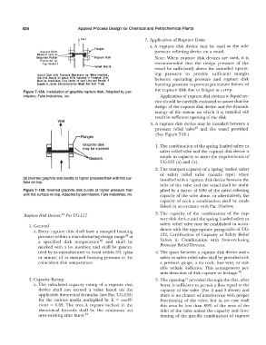
Neaprene Rubber�--,,1,,1!!!!1' Rupture Disk Note: When rupture disk devices are used, it is
Preferred for
Top Gaskel.J recommended that the design pressure of the
Vessel Nozzle
vessel be sufficiently above the intended operat-
Install Disk with Pressure Mtmbrone up. When inverted, ing pressure to provide sufficient margin
the Disk Bursts ot about 65% Increase in Pressure. Disk between operating pressure and rupture disk
Must be Positioned True Center al Vent Line and Norrie. II
Eccentric, Burst Characteristics Might Not Hold True. bursting pressure to prevent premature failure of
the rupture disk due to fatigue or creep.
Figure 7-13A. Installation of graphite rupture disk. Adapted by per-
mission, Falls Industries, Inc. Application of rupture disk devices to liquid ser-
vice should be carefully evaluated to assure that the
design of the rupture disk device and the dynamic
energy of the system on which it is installed will
result in sufficient opening of the disk.
Vent b. A rupture disk device may be installed between a
i pressure relief valve 48 and the vessel provided.
(See Figure 7-10.)
1. The combination of the spring loaded safety or
safety relief valve and the rupture disk device is
I t F Gaskets ample in capacity to meet the requirements of
UG-133 (a) and (b).
2. The stamped capacity of a spring loaded safety
or safety relief valve (nozzle type) when
(b) Inverted graphite disk bursts at higher pressure than with flat sur- installed with a rupture disk device between the
face on top.
inlet of the valve and the vessel shall be multi-
Figure 7-138. Inverted graphite disk bursts at higher pressure than plied by a factor of 0.80 of the rated relieving
with flat surface on top. Adapted by permission, Falls Industries, Inc. capacity of the valve alone, or alternatively, the
capacity of such a combination shall be estab-
lished in accordance with Par. 3 below;
Rupture Disk Devices, 44 Par UG-127 3. The capacity of the combination of the rup-
ture disk device and the spring loaded safety or
1. General safety relief valve may be established in accor-
a. Every rupture disk shall have a stamped bursting dance with the appropriate paragraphs of UG-
pressure within a manufacturing design range 35 at I 32, Certification of Capacity of Safety Relief
a specified disk temperature 36 and shall be Valves in Combination with Non-reclosing
marked with a lot number, and shall be guaran- Pressure Relief Devices.
teed by its manufacturer to burst within 5% (plus 4. The space between a rupture disk device and a
or minus) of its stamped bursting pressure at the safety or safety relief valve shall be provided with
coincident disk temperature. a pressure gauge, a try cock, free vent, or suit-
able telltale indicator. This arrangement per-
mits detection of disk rupture or leakage. 19
2. Capacity Rating 5. The opening"? provided through the disk, after
a. The calculated capacity rating of a rupture disk burst, is sufficient to permit a flow equal to the
device shall not exceed a value based on the capacity of the valve (Par. 2 and 3 above) and
applicable theoretical formulas (see Par. UG-131) there is no chance of interference with proper
for the various media multiplied by K = coeffi- functioning of the valve; but in no case shall
cient = 0.62. The area A (square inches) in the this area be less than 80% of the area of the
theoretical formula shall be the minimum net inlet of the valve unless the capacity and func-
area existing after burst. 47 tioning of the specific combination of rupture