
Page 460 - APPLIED PROCESS DESIGN FOR CHEMICAL AND PETROCHEMICAL PLANTS, Volume 1, 3rd Edition
P. 460
426 Applied Process Design for Chemical and Petrochemical Plants
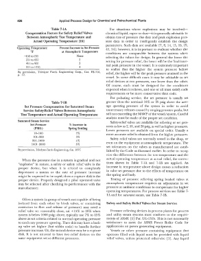
Table 7-IA For situations where explosions may be involved-
Compensation Factors for Safety Relief Valves chemical liquid, vapor or dust-it is generally advisable to
Between Atmospheric Test Temperature and obtain rate of pressure rise data and peak explosion pres-
Actual Operating Temperature [24] sure data in order to intelligently establish the design
parameters. Such data are available [7, 8, 14, 15, 16, 19,
Operating Temperature Percent Increase in Set Pressure 41, 54]; however, it is important to evaluate whether the
OF at Atmospheric Temperature conditions are comparable between the systems when
-450 to 200 None selecting the values for design. In general the lower the
201 to 450 2 setting for pressure relief, the lower will be the final inter-
451 to 900 3 nal peak pressure in the vessel. It is extremely important
901 to 1200 4
to realize that the higher the system pressure before
By permission, Teledyne Farris Engineering Corp., Cat. FE-316, relief, the higher will be the peak pressure attained in the
p. 12.
vessel. In some difficult cases it may be advisable to set
relief devices at two pressures, one lower than the other.
Of course, each must be designed for the conditions
expected when it relieves, and one or all must satisfy code
requirements or be more conservative than code.
For pulsating service, the set pressure is usually set
Table 7-lB greater than the nominal 10% or 25 psig above the aver-
Set Pressure Compensation for Saturated Steam age operating pressure of the system in order to avoid
Service Safety-Relief Valves Between Atmospheric unnecessary releases caused by surging pressure peaks, but
Test Temperature and Actual Operating Temperature still not exceeding the MAv\lP of the vessel/ system. Careful
analysis must be made of the proper set condition.
Saturated Steam Service Safety-relief valves are available for relieving or set pres-
Set Pressure % Increase in sures as low as 2, 10, and 20 psig, as well as higher pressures.
(PSIG) Spring Settling
Lower pressures are available on special order. Usually a
10-100 2% more accurate relief is obtained from the higher pressures.
101-300 3% Safety relief valves are normally tested in the shop, or
301-1000 4%
1001-3000 5% even on the equipment at atmospheric temperature. The
set tolerances on the valves as manufactured are estab-
By permission, Teledyne-Farris Engineering, Cat. 187C lished by the Code as discussed earlier. In order to recog-
nize the difference between the test temperature and the
When the pressure rise in a system is gradual and not actual operating temperature at actual relief, the correc-
"explosive" in nature, a safety or safety relief valve is the tions shown in Table 7-lA and 7-lB are applied. An
proper device, but when it is critical to completely increase in temperature above design causes a reduction
depressure a system or the rate of pressure increase in valve set pressure due to the effects of temperature on
might be expected to be rapid, then a rupture disk is the the spring and body.
proper device. Properly designed a pilot operated valve Testing of pressure relieving spring loaded valves al
may be selected after checking its performance with the atmospheric temperature requires an adjustment in set
manufacturer. pressure at ambient conditions to compensate for higher
operating temperatures. For process services see Table 7-
lA and for saturated steam, use Table 7-1 B.
Often a system (a group of vessels not capable of being
isolated from each other by block valves, or containing Safety and Safety Relief Valves for Steam Service
restriction to flow and release of pressure) may need a
relief valve set reasonably close, sat + 15% to 20% when Pressure relieving devices in process plants for process
system is below 1000 psig; above, typically use 7% to 15% and utility steam systems must conform to the require-
above as set criteria related to normal operating pressure ments of ASME [l] Par. UG-131b. This is not necessarily
to catch any pressure upswing. Then this may have a back- satisfactory to meet the ASME Power Boiler Code for
up valve set higher (but within code) to handle further applications on power generating equipment.
pressure increase. Or, the second device may be a rupture Vessels or other pressure containing equipment that
disk. It is not unusual to have two relief devices on the operates filled with liquid must be provided with liquid
same equipment set at different pressures. relief valves, unless protected otherwise [l]. Any liquid