
Page 457 - APPLIED PROCESS DESIGN FOR CHEMICAL AND PETROCHEMICAL PLANTS, Volume 1, 3rd Edition
P. 457
Process Safety and Pressure-Relieving Devices 423
• Vessels operating completely filled with liquid must
be equipped with liquid relief valves, unless otherwise
protected (Par. UG-125-3(g).
• Safety and safety relief valves for steam service should
meet the requirements of ASME Par. UG-131 (b), Ref
(1]. Note that the requirements for these valves are
slightly different than for process type valves.
Relieving Capacity of Combinations of Safety Relief Valves and
Rupture Disks or Non-Reclosure Devices (Reference ASME
Code, Par. UG-127, UG-132).
• Primary Relief
A single rupture disk can be used as the only over-
pressure protection on a vessel or system (Figure 7-10).
Figure 7-11. Safety valve and rupture disk installation using pres-
sure rupturing disk on inlet to safety relief valve, and low pressure The disk must be stamped by the manufacturer with
disk on valve discharge to protect against back flow/corrosion of the guaranteed bursting pressure at a specific tempera-
fluid on valve discharge side, possibly discharge manifold. By per- ture. The disk must rupture within ±5% of its stamped
mission, Fike Metal Products Div., Fike Corporation, Inc. bursting pressure at its specified burst temperature of
operation. The expected burst temperature may need
ting requirements of Par. UG-134(a) are met. See Par. to be determined by calculation or extrapolation to be
(A) 1 and 2 above and see Figure 7-7A. consistent with the selected pressure.
The set burst pressure should be selected to per-
mit a sufficiently wide margin between it and the ves-
When pressure relief devices are intended primar- sel's used or design operating pressure and tempera-
ily for protection against overpressure due to exter- ture to avoid premature failure due to fatigue or
nal fire or heat, have no permanent supply connec- creep of metal or plastic coatings.
tion, and are used for storage at ambient
temperature of non-refrigerated liquefied com- Selected Portions of ASME Pressure Vessel Code, quoted l1y
pressed gases, they are excluded from requirements permission [I]
of Par. UG-125c (1) and C (2), with specific provi-
sions. See ASME code (1) for detailed references and Section VIII, Division I Superscript = Footnote reference
conditions. July I, /989 Edition in Code Figure No., for this text.
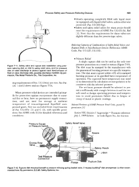
Safety Relief Valve
I ·J-Bolt
Test Pressure
Connection
Figure 7-12. Rupture disk mounted beneath a pressure relieving spring-loaded valve. A reverse buckling® disk arrangement is often recom-
mended here. By permission, B.S.&B. Safety Systems, Inc.