
Page 496 - APPLIED PROCESS DESIGN FOR CHEMICAL AND PETROCHEMICAL PLANTS, Volume 1, 3rd Edition
P. 496
462 Applied Process Design for Chemical and Petrochemical Plants
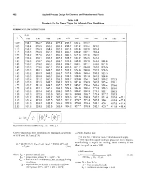
Table 7-11
Constant, C 2, for Gas or Vapor for Subsonic Flow Conditions
SUBSONIC FLOW CONDITIONS
p,;p.
k 0.95 0.90 0.85 0.80 0.75 0.70 0.65 0.60 0.55 0.50 0.45
1.001 158.1 214.7 251.9 277.8 295.7 307.4 313.7
1.05 158.4 215.5 253.3 280.0 298.7 311.2 318.4 321.0
1.10 158.7 216.3 254.7 282.0 301.5 314.8 322.9 326.4
1 .15 158.9 216.9 255.9 283.9 304.1 318.2 327.1 331.4
1.20 159.2 217.6 257.0 285.6 306.5 321.3 331.0 336.0
1.25 159.4 218.1 258.1 287.2 308.7 324.2 334.5 340.4
1.30 159.6 218.7 259.1 288.7 310.8 326.9 337.9 344.4 346.8
1.35 159.7 219.2 260.0 290.1 312.7 329.4 341.1 348.2 351.3
1.40 159.9 219.6 260.8 291.4 314.5 331.7 344.0 351.8 355.5
1.45 160.0 220.1 261.6 292.6 316.2 334.0 346.8 355.2 359.5
1.50 160.2 220.5 262.3 293.7 317.8 336.0 349.4 358.3 363.3
1.55 160.3 220.8 263.0 294.8 319.3 338.0 351.8 361.3 366.8
1.60 160.4 221.2 263.7 295.8 320.7 339.8 354.1 364.2 370.2 372.3
1.65 160.6 221.5 264.3 296.7 322.0 341.6 356.3 366.8 373.4 376.1
1.70 160.7 221.8 264.8 297.6 323.2 343.2 358.4 369.4 376.4 379.6
1.75 160.8 222.1 265.4 29J.5 324.4 344.8 360.4 371.8 379.3 383.0
1.80 160.9 222.4 265.9 299.3 325.5 346.2 362.3 374.1 382.1 386.3
1.90 161.0 222.9 266.9 300.7 327.6 349.0 365.7 378.4 387.2 392.3
2.00 161.2 223.4 267.7 302.1 329.5 351.5 368.9 382.3 391.8 397.8 400.1
2.10 161.4 223.8 268.5 303.3 331.2 353.7 371.8 385.8 396.1 402.8 405.9
2.20 161.5 224.2 269.2 304.4 332.8 355.8 374.4 389.1 400.1 407.5 411.4
2.30 161.6 224.5 269.9 305.4 334.2 357.7 376.9 392.1 403.7 411.8 416.4
k
G.! = 735
k-1
By permission Continental Disc Corp., Cat. 1-1110, p. 1.
Converting actual flow conditions to standard conditions Liquids: Rupture disk
of60°F and 14.7 psia [73]:
The test for critical or non-critical does not apply.
These equations apply to single-phase (at inlet) liquids,
non-flashing to vapor on venting, fluid viscosity is less
Q. = [{(520/14.7)) (Pac/Tac,)] (Qlct) = SCFM, 60°F and than or equal to water [69].
14. 7 psia (7-44)
ASME mass flow :
where P,c, = pressure actual, psia A= -------;:::W==== , sq m. (7-45)
.
2
Tact= temperature actual, °F + 460°F = R 2407 Kd � (Pb - P )P 1
0
<2ac, = flow at actual conditions: ACFM, at actual flowing
conditions where W = flow, lb/hr
Q, = required flow, cu ft/min at standard conditions p = Fluid density, lb/ cu ft
( 14. 7 psia at 60°F), ( 60°F + 460 = 520°R) K,i = coefficient of discharge = 0.62