Page 513 - APPLIED PROCESS DESIGN FOR CHEMICAL AND PETROCHEMICAL PLANTS, Volume 1, 3rd Edition
P. 513

Applied Process Design                                     479

                                                                3. Control valve failure
                                                                4. Vapor displacement during filling
                                                                5. Withdrawal  of stored liquid at maximum rate  (refer
                                                                  to section on non-refrigerated tanks)
                                                                6. Withdrawal  of vapor  at  maximum  compressor  suc-
                                                                  tion rate.
                                                                7.  Drop of barometric pressure.


                                                                Under some  circumstances  it may  not be  appropriate
                        Figure 7-39A. Continued.              to  allow  air to  enter  (inbreathe)  into  the  tank,  then  the
                                                              use  of some  other inert gas,  such as  nitrogen  or natural
                                                              gas,  is  acceptable  on  a  pressure  control  basis;  however,
           The capacity of pressure-vacuum devices for a tank are   this cannot take  the place of a vacuum relieving device to
        to  be  determined  at  110%  of  their  "start  to  discharge"   allow air to enter under a final  emergency condition.
        pressure. Except for emergency pressure relieving because
        of fire, the capacity may be determined at 120%  [26].

        Normal conditions                                     Emergency  Venting  far Fire Exposure
           At least the following conditions or some combination   For refrigerated tanks  the total  venting requirement is
        must be considered in  establishing  the normal  pressure-   the value determined from Table 7-17,  multiplied by  the
        vacuum relief capacity requirements  [26]:            environment factor F from Table 7-18.  For tanks  greater
                                                              than  2,800  ft. 2   exposed  wetted  surface,  use  the  venting
           1. Loss of refrigeration                           formula for Ve  (Equation  7-49). Do not apply  the factors
           2.  Liquid overfilling                             from Table 7-18.


                                   �'
                                  It  ''f
                                  I  ,,,p,7
                                  J
                                t: "-�t''i
                                 J,,,  ...  /,�-'?;,,
                                 ,,   t, fi'r/--1-'
                                     �
                                /1,'.1•1 '              \
                                 I   1,  /1,1
                                /I   ,'  1/d
                               JI   ,I  '11/
                               1 1   11 1·,
                               1/  ,'! 1/,)
                              ,,  ,,,,,,         +  0
                              /1  I   ,,,,,,  '11   750 _  50
                                 ff  l{t/
                                                  \
              r             II  /t  •.  Jiii        I  I.   I      I   -------
                              I'  //II//
                             /1
                                I  I  I I
                             ,,
                               ,I  II/
                             /I
                            JI
                                 I
                                                                                -
                                 •
                              I
              A            FIL      I                                           E
              l                  :                                            -N
                                                                              ij
                                 :                                            :
                                 I                                            I  I
                                 I.                    K                     J
                                 '
                                                       c
                                                       B
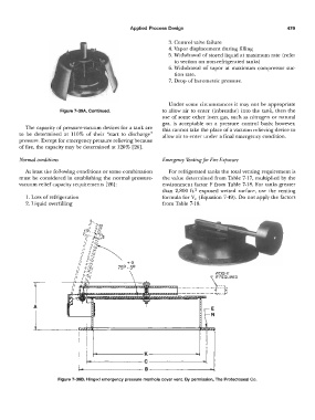
                       Figure 7-398. Hinged emergency pressure  manhole cover vent.  By permission, The Protectoseal Co.
   508   509   510   511   512   513   514   515   516   517   518