
Page 511 - APPLIED PROCESS DESIGN FOR CHEMICAL AND PETROCHEMICAL PLANTS, Volume 1, 3rd Edition
P. 511
Applied Process Design 477
that the stored liquid has the physical and ther- Note that the above formula is based on the one in API-
mal characteristics of hexane. RP-520 [10]:
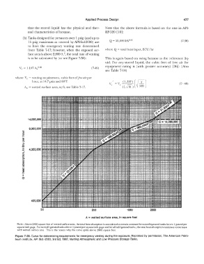
(b) Tanks designed for pressures over 1 psig (and up to
15 psig maximum as covered by API-Std-2000) are Q = 21,000 FA 0·82 (7-30)
to have the emergency venting rate determined
from Table 7-17; however, when the exposed sur- where Q = total heat input, BTU/hr
face area is above 2,800 ft. 2, the total rate of venting
is to be calculated by ( or see Figure 7-38): This is again based on using hexane as the reference liq-
uid. For any stored liquid; the cubic feet of free air for
equipment rating is (with greater accuracy) [26]: (Also
Ve = 1,107 A" 0·82 (7-49)
see Table 7-14)
where Ve = venting requirement, cubic feet of free air per
hour, at 14. 7 psia and 60° F, (
V = V (1,337) rJ;) (7- 48)
A,,. = wetted surface area, sq fl, see Table 7-17. c e (LfM) I 520
14,090,000
.. 9,950,000
:::,
0
.c
i
:::,
ai
c
.2
�
j
=
j
•
0
20 200 1000 2800
A .. wetted surface area, In square feet
NOTE: Above 2800 square feet of wetted surface area, the total heat absorption is considered to remain constant for nonrefrigerated tanks below I pound per
square inch gage. For nonrefrigeratcd tanks above I pound per square inch gage and for all refrigerated tanks, the total heat absorption continues to increase
with wetted surface area. This is the reason why the curve splits above 2800 square feet.
Figure 7-38. Curve for determining requirements for emergency venting during fire exposure. Reprinted by permission, The American Petro-
leum lnstitute, API Std.-2000, 3rd Ed. 1987, Venting Atmospheric and Low Pressure Storage Tanks.