
Page 512 - APPLIED PROCESS DESIGN FOR CHEMICAL AND PETROCHEMICAL PLANTS, Volume 1, 3rd Edition
P. 512
478 Applied Process Design for Chemical and Petrochemical Plants
where Ve = cubic feet of free air /hr from Table 7-17 or Equa- Due to the importance of complying with all standards
tion 7-49 for any fluid. and regulations, and the necessary reduction in detail in
L = latent heat of vaporization of liquid, BTU /lb such a summary as presented here, it is recommended that
M = molecular weight of liquid the ASME, API and NFPA standards and codes be consult-
ed for final design detail and installation conformity.
T = temperature of the relief vapor, R
0
Refer to API-2000 [26] for recommendation regarding
The vent size may be determined based on the pres- installation requirements. Tank venting equipment capac-
sure that the tank can safely withstand [26]. ities are expressed as free air /hour. For handling other
fluids besides hexane or gasoline, use equation for V'c
The code [26] allows a credit or reduction of required
emergency venting for specific conditions. The final total (Equation 7-48) to convert to equivalent free air flow.
emergency venting requirements may be determined as:
Emergency Vent Equipment
*To Obtain Final Value,
Condition Multiply Previous Ve by There are several types available as illustrated in Fig-
Drainage is away from tank 0.5 ures 7-39A, B, and C. See Figure 7-40 for specifications
Tank has I" external insulation 0.3 worksheet.
Tank has 2" external insulation 0.15
Tank has 4" external insulation 0.075
Tank has water spray" 1.0 Refrigerated Above Ground and Below Ground Tanks [26]
*Insulation values based on conductance of 4 BTU/hr-ft 2 -°F/in. and The presence of low temperature conditions creates
insulation must be capable of withstanding fire hose streams without
dislodging, and must be non-combustible. additional problems in design and selection of relieving
+Water spray is not considered reliable, so no reduction is allowed . devices, primarily because of the possibility of ice formation.
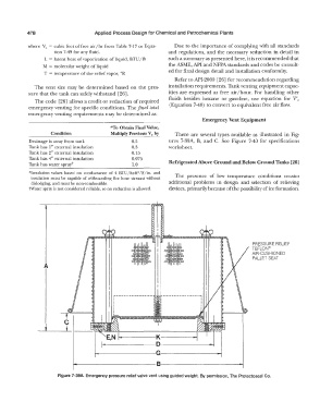
•• PRESSURE RELIEF
TEFLON®
AIR-CUSHIONED
PALLET SEAT
A
,--------------, r--------------,
I I I I
I I I I
I I I I
I I I I
I I
I I I
i--------K----------
i----------�0-------
..-.-----------�-------
-----------------�B�---------------'-
Figure 7-39A. Emergency pressure relief valve vent using guided weight. By permission, The Protectoseal Co.