
Page 514 - APPLIED PROCESS DESIGN FOR CHEMICAL AND PETROCHEMICAL PLANTS, Volume 1, 3rd Edition
P. 514
480 Applied Process Design for Chemical and Petrochemical Plants
SIDE VIEW
I I
t---����������-K����������---i
�---��������������·C���������������•-i
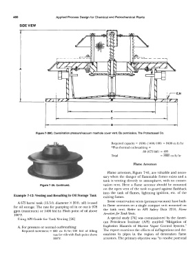
Figure 7-39C. Combination pressure/vacuum manhole cover vent. By permission, The Protectoseal Co.
Required capacity= (600) (1400/100) = 8400 cu ft/hr
*Plus thermal outbreathing =
.60 (675 bbl) = 105
Total = 8805 cu ft/hr
Flame Arrestors
Flame arrestors, Figure 7-41, are valuable and neces-
sary when the danger of flammable fumes exists and a
tank is venting directly to atmosphere, with no conser-
Figure 7-39. Continued. vation vent. Here a flame arrestor should be mounted
on the open vent of the tank to guard against flashback
into the tank of flames, lightning ignition, etc. of the
Example 7-12: Venting and Breathing in Oil Storage Tank exiting fumes.
Some conservation vents (pressure-vacuum) have built-
A 675 barrel tank (15.5 ft. diameter X 20 ft. tall) is used
for oil storage. The rate for pumping oil in or out is 978 in flame arrestors on a single compact unit mounted on
gpm (maximum) or 1400 bbl hr. Flash point of oil above the tank vent. Refer to API Safety Data 2210, Flame
I00°F. Arrestors for Tank Vents.
Using API Guide for Tank Venting [26] A special study [74] was commissioned by the Ameri-
can Petroleum Institute (API) entitled "Mitigation of
A. For pressure or normal outbreathing: Explosion Hazards of Marine Vapor Control Systems."
Required movement= 600 cu ft/hr/100 bbl of filling The report examines the effects of deflagrations and det-
rate for oils with flash point above onations in pipes in the region of detonation flame
l00°F. arrestors. The primary objective was "to resolve potential