
Page 557 - APPLIED PROCESS DESIGN FOR CHEMICAL AND PETROCHEMICAL PLANTS, Volume 1, 3rd Edition
P. 557
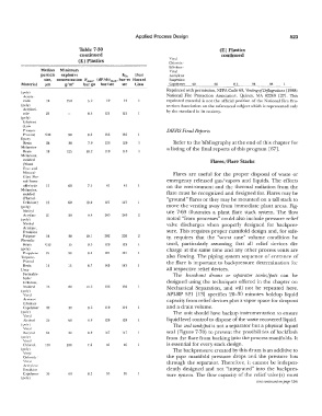
Applied  Process Design                                    523

                               Table 7-30                                            (E) Plastics
                               continued                                             continued
                               (E) Plastics                       Vinyl
                                                                  Chlonde/
                                                                  Erhvlcnc.'
                 Median   Minimum                                 Vinyl
                 particle   explosive           Ks,   Dust        Acetylene
                  size,  concenrrarion  Pmu•  (dP/dl)mu, bar-m  Hazard   Swpension
         Material   iim   g/m'   bar ga   bar/sec   sec   Class   �mer    60       60     8.3    98     98   1
                                                                 Reprinted with permission, NFPA Code 68,  Venting of  Deflagrations ( 1988)
         (poly)
          Acryla-                                                National  Fi1·e  Protection  Association,  Quincy,  MA  02269  [27].  This
          mide     IO     250      5_9    12    12               reprinted material is  not  the  official  position  of the National  Fire  Pro-
         (poly}                                                  tection Association on the referenced subject which is  represented only
          Acryloni-
          rrile    25              8.5   121    121              by  the standard in its entirety.
         (poly)
          Ethylene
          (Low
          Pressure                                               DIERS Final Reports
          Process)   <IO   so      8.0   156    156
         Epoxy
          Resin    26      30      7.9   129    129                Refer to the bibliography at the end of this chapter for
         Melamine                                                a listing of the final reports of this program  [67].
          Resin    18      125    10.2   110    110
         Melamine.
          molded                                                                 Flares/Flare Stacks
          (Wood
          flour and
          Mineral-                                                 Flares  are  useful  for  the  proper disposal  of waste  or
          filled  Phe-
          nol-Form-                                              emergency  released  gas/vapors  and  liquids.  The  effects
          aldehyde   15    60      7.5    41    41               on  the environment and the  thermal  radiation from the
         Melamine,
             0
          molded                                                 flare must be recognized and designed for.  Flares may be
          (Phenol-                                               "ground" flares or they may be mounted on a tall stack to
          Cellulose)   12   6()   10.0   127    127
         (poly)                                                  move  the venting away from  immediate  plant areas.  Fig-
          Methyl                                                 ure  7-69  illustrates  a  plant flare  stack  system.  The  flow
          Acrylate   21    30      9.4   269    269
         (poly)                                                  noted  "from  processes" could also  include pressure  relief
          Methyl                                                 valve  discharges  when  properly  designed  for  backpres-
          Acrylate,
          Emulsion                                               sure. This requires proper manifold design and,  for safe-
          Polymer   18            10.l   202    202   2          ty,  requires  that  the  "worst  case"  volume  condition  be
         Phenolic
          Resin   <10      15      9.3   129    129              used,  particularly  assuming  that  all  relief  devices  dis-
         (poly)                                                  charge  at the same  time and any  other process vents  are
          Propylene   25   30     8.4    101    IOI
         Terpcne-                                                also flowing.  The  piping system sequence  of entrance  of
          Phenol                                                 the flare is  important to  backpressure  determination  for
          Resin    lO      1:,     8.7   143    143
         Urea-                                                   all respective relief devices.
          Formalde                                                 The  knock-out  drums  or  separator  tanks/pots  can  be
          hyde/
          Cellulose.                                             designed using the techniques  offered in the  chapter on
          Molded   13      60     10.2   136    136              Mechanical  Separation,  and  will  not  be  repeated  here.
         (poly)
          Vinyl                                                 API-RP  521  [13]  specifies  20-30  minutes  holdup  liquid
          Acct ate/                                              capacity from relief  devices plus a vapor space for dropout
          Ethylene
          Copclymer   32   30      8.6   119    119              and a drain volume.
         (polv)                                                    The unit should have backup instrumentation to ensure
          Vinyl
          Alcohol   25     60      8.9   128    128              liquid level control to dispose of the waste recovered liquid.
         (polv)                                                    The seal tank/pot is not a separator but a physical  liquid
          Vinyl
          Bur yr  al   63   30    8.9    147    14 i             seal  (Figure 7-70)  to prevent the possibilities of backflash
         (poly)                                                  from the flare from backing into the process manifolds.  It
          Vinyl
          Chloride   1 Oi   200    7.6    •16   46               is essential for every stack design.
         (poly)                                                    The backpressure created by this drum is an additive to
          Vinyl
          Chloride'                                              the  pipe  manifold  pressure  drops  and  the  pressure  loss
          Vinyl                                                  through  the  separator.  Therefore,  it cannot be  indepen-
          Accr yk-ne
          Emulsion                                               dently  designed  and  not "integrated"  into  the  backpres-
          Copolymer   3:>   60    8.2                            sure  system.  The flow  capacity of the  relief valve(s)  must
         (polv)
                                                                                                   (Cexl continued on page  526)