
Page 555 - APPLIED PROCESS DESIGN FOR CHEMICAL AND PETROCHEMICAL PLANTS, Volume 1, 3rd Edition
P. 555
Applied Process Design 521
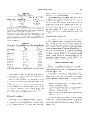
Table 7-28 released material (dusts, gases, or mixtures), which may
Hazard Class for Dusts be very hot, can be safely released.
Ks 1 *Max. Rate Pressure Rise First and foremost these venting ducts should be as
Hazard Class Bar meter/sec lbr/in /sec straight as possible, with few, if any elbows, and even these
2
��------------------� should be sweeping bends. There should be no valves of
St-I > 0 � 200 < 7300
St-2 201-300 7300-22,000 any type to keep flow resistance as low as possible, as this
St-3 > 300 > 22,000 creates friction that creates backpressure on the relief
St-0 0, non-combustible device and raises burst conditions, which can be terribly
dangerous. Figure 7-66 and 7-67 are used to assess the
Note: The nomographs are limited to an upper K,t value of 600. Kst val- increased pressure due to ducts on relief discharge as
ues determined in an approximate spherical test vessel of at least 20 liter
capacity. See Tables 7-29 and 7-30 for typical Ksr values. affected by duct length. (This data is limited. See Ref. [56
Reprinted with permission, NFPA Code 68, Venting of Deflagrations ( 1988) and 53] .)
National Fire Protection Association, Quincy, NI.A 02269 [27]. This
reprinted material is not the official position of the National Fire Pro- Maximum Distance Between Vents
tection Association on the referenced subject which is represented only
by the standard in its entirety. Figure 7-68 indicates the maximum allowable distance
*Added by this author.
between vents on a vessel or pipe related to vent diameter
Table 7-29 when multiple vents are required. When distances are
K 5 cvalues of Technical Fine Dust s -High Ignition Energy greater than indicated, a detonation should be anticipat-
ed in the design of the equipment strength. Figure 7-68 is
pmax Kscvalue applicable for systems with operating pressures up to 0.2
Type of dust (bar) (bar · m · s - 1)
bar ga and for systems such as elongated vessels, pipes,
PVC 6.7-8.5 27-98 and ducts with dusts or gases that are vented at one end,
Milk powder 8.1-9.7 58-130 and have a velocity of less than 2 meters per second.
Polyethylene 7.4-8.8 54-131 Above 2 meters per second, alternate protection is rec-
Sugar 8.2-9.4 59-165 ommended because a detonation is likely [27] [56]. See
Resin dust 7.8-8.9 108-174
Brown coal 8. l-10.0 93-176 NFPA-68, Ref. [27] for details of application.
Wood dusts 7.7-10.5 83-211
Cellulose 8.0-9.8 56-229 Runaway Reactions: DIERS
Pigments G.5-10.7 28-344
Aluminum 5.4-12.9 16-750 There is no standardized method for predicting or
controlling runaway reaction that may lead to explosions
By permission, Bartknecht, W .. Explosions, 2nd Ed. ( 1980) Springer-Verlag.
( deflagrations or detonations), except possibly the Fauske
approach (Figure 7-61).
Accordingly, to emphasize the safety problems affect-
These clouds can travel with the prevailing wind cur- ing all industrial process plants and laboratories, the
rents and thereby explode considerable distances from American Institute of Chemical Engineers established the
the initial discharge of vapors. industry-supported Design Institute for Emergency Relief
Reference [ 40] presents a rather thorough review of Systems. The purposes of the Institute are [51]:
the history and theoretical analysis of these types of explo-
sions. • Reduce the frequency, severity, and consequences of
Atmosphere releases may form relatively still clouds, or pressure producing accidents
they may plume and trail with the wind, or they may jet • Promote the development of new techniques that will
high into the atmosphere before forming a cloud, all improve the design of emergency relief systems.
depending to some extent on the unit. Wells [53] pre- • Understand runaway reactions.
sents a thorough analysis of these phenomena.
• Study the impact of two-phase flow on pressure reliev-
ing device systems.
Effects of Venting Ducts
The research and technical evaluations have provided
Usua!ly the relief of explosions cannot readily, safely, or industry with extremely valuable information and design
conventionally be released right at the source, whether in procedures, including, but not limited to, two-phase flow
a building or in a working plant area. Therefore, these phenomena and runaway reactions during safety I over-
reliefs are directed to some discharge point where the pressure relief.