Page 560 - APPLIED PROCESS DESIGN FOR CHEMICAL AND PETROCHEMICAL PLANTS, Volume 1, 3rd Edition
P. 560

526                       Applied Process Design for Chemical  and Petrochemical  Plants
                                                        --
               5.0                               _ i__.-  _ ..

               2.5                       -  -        _ ...
               2.0                              ......
                            �
            ..:-   �                    .......  .. ---·
            ca
            e  1.0               ......   --
            ..s
            u           ............. ------
            ::,
            "O   0.5  ...  .... -
            .s=
            .'!:::              Gases
            a::
             �                  - Duct Length > 3 m
            D.                  ----- Duct Length � 3 m
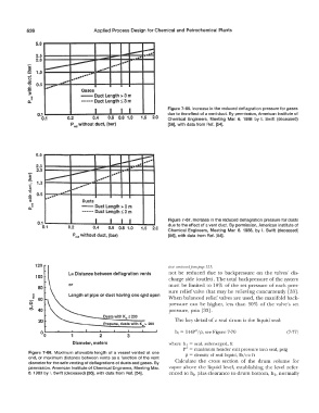
                                      I    I   I  I              Figure 7-66.  Increase in the reduced deflagration pressure for gases
               0.1                                               due to the effect of a vent duct.  By permission, American Institute of
                 0.1       0.2       0.4   0.6  0.8  1.0   1.5  2.0   Chemical  Engineers,  Meeting  Mar.  6,  1988  by  I.  Swift  (deceased)
                            P  without duct, (bar)                [56], with data from Ref.  [54].
                             red


               5.0                          --  _..  ---  �
                                                          ....
                                                        ....
               2.5                    -            ..   ....
               2.0                      .... -
            ..:-            :...---         ----
            ,e.   �                    __
               1.0               .... -
            ti               ...........
            ::,          ........
            'O   0.5   .... -
            :5     .....
            '!!:                 Dusts
             "
            D. �                - Duct Length > 3 m
                                 ----- Duct Length s 3 m
               0.1                    I    I    I   I             Figure 7-67.  Increase in the reduced deflagration  pressure for dusts
                 0.1       0.2       0.4   0.6  0.8  1.0   1.5   2.0   due to the effect of a vent duct.  By permission, American Institute of
                                                                  Chemical  Engineers,  Meeting  Mar.  6,  1988,  by  I.  Swift  (deceased)
                             P  red without duct,  (bar)          [56], with data from  Ref.  [54].


               120                                                (trx!  continued from  page 523)
                           L= Distance between deflagration vents   not be  reduced  due  to  backpressure  on  the  valves'  dis-
               100
                                                                  charge side  (outlet). The total backpressure of the system
                           or                                     must be  limited  to  10%  of the set pressure  of each pres-
                80
                                                                  sure  relief valve  that may  be relieving concurrently  [33].
              i            Length of pipe or duct having one e[!d open   When balanced relief valves are used,  the manifold back-
            s   60                                                pressure  can  be  higher,  less  than  30%  of the valve's  set
            :::i
            .._..
                40                                                pressure,  psia  [33].
                                         Dusts with K., :!: 200
                20                                                  The key detail of a seal  drum is the liquid seal:
                                         Propane, dusts with  K., >  200
                 00         1          2          3                 h,  =  144P"/p, see Figure  7-70           (7-77)

                             Diameter,  meters                    where  h.  =  seal, submerged,  ft
                                                                       P" =  maximum header exit pressure  into  seal,  psig
            Figure  7-68.  Maximum  allowable  length  of a  vessel  vented  at one   p  =  density of seal liquid,  lb/ cu ft
            end,  or maximum distance between vents as a function  of the vent   Calculate  the  cross  section  of  the  drum  volume  for
            diameter for the safe venting of deflagrations of dusts and gases. By
            permission, American  Institute of Chemical  Engineers,  Meeting Mar.   vapor above  the  liquid  level,  establishing  the level  refer-
            6,  1988 by I.  Swift (deceased) [56], with data from  Ref.  [54].   enced to h., plus clearance to drum bottom,  h., normally
   555   556   557   558   559   560   561   562   563   564   565