
Page 561 - APPLIED PROCESS DESIGN FOR CHEMICAL AND PETROCHEMICAL PLANTS, Volume 1, 3rd Edition
P. 561
Applied Process Design 527
cle diameter [ (2) (inlet pipe)]. Thus, the cross-section
area of vapor space A. with equivalent diameter S should
Latu be at least [ (2) (ap)] where ap is the cross-sectional area of
the inlet pipe [33]. To avoid bubble burst slugging, this
author suggests that the cross-sectional area of S be calcu-
lated to have a vapor velocity of less than the entrainment
EM!
ll•ra velocity for a mist sized liquid particle, or that the vapor
at.ck
b¥o=• area be approximately one-third the cross-section area of
the diameter of the horizontal drum. For a vertical drum,
Ref. [33] recommends that the vapor disengaging height
K�
be three feet.
When vacuum can form in the system due to condens-
ing/ cooling hot vapor entering, the seal drum liquid vol-
ume and possibly the seal drum diameter /length must be
,._....... adjusted to maintain a seal when/if the seal fluid is drawn
up into the inlet piping. A vacuum seal leg should be pro-
----- _,.,_, vided on the inlet 1.2 times the expected equivalent vacu-
Figure 7-69. Illustration of one of many collection arrangements for um height in order to maintain a seal.
process flow and/or relief valve discharge collections to relieve to The following design points should be considered:
one or more plant flare stacks. By permission, Livingston, D. D., Oil
& Gas Jour., Apr. 28, 1980. • Provide liquid low level alarms to prevent loss of liq-
uid by evaporation, entrainment, leaks, or failure of
the makeup liquid system.
12 inches to 18 inches. This would be a segment (hori-
zontal vessel) of a circle (see Appendix Table 24). Ref. • Use a sealing liquid that has a relatively low vapor
[33] recommends that the cross section area of the vapor pressure, and is not readily combustible, and will not
space above the liquid be at least equivalent to that of a cir- readily freeze. Quite often glycol or mixtures are
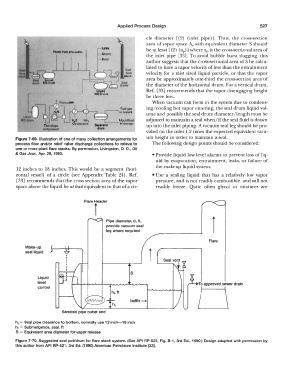
Pipe diameter, d, ft,
provide vacuum seal
leg where required
Flare
Make-up
r
seal liquid
.,
-,--- s
I
I
Liquid
level
control
baffle-
Serrated pipe outlet end
hL = Seal pipe clearance to bottom, normally use 12 inch-18 inch
h 1 = Submergence, seal, ft
S = Equivalent area diameter for vapor release
Figure 7-70. Suggested seal poVdrum for flare stack system. (See API RP-521, Fig. 8-1, 3rd Ed., 1990.) Design adapted with permission by
this author from API RP-521, 3rd Ed. (1990) American Petroleum Institute (33].