
Page 332 - REPOWER REFERENCE GUIDE (2020)
P. 332
Steering Systems
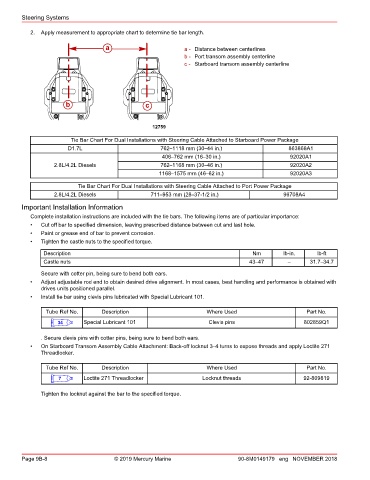
2. Apply measurement to appropriate chart to determine tie bar length.
a a - Distance between centerlines
b - Port transom assembly centerline
c - Starboard transom assembly centerline
b c
12759
Tie Bar Chart For Dual Installations with Steering Cable Attached to Starboard Power Package
D1.7L 762–1118 mm (30–44 in.) 863868A1
406–762 mm (16–30 in.) 92020A1
2.8L/4.2L Diesels 762–1168 mm (30–46 in.) 92020A2
1168–1575 mm (46–62 in.) 92020A3
Tie Bar Chart For Dual Installations with Steering Cable Attached to Port Power Package
2.8L/4.2L Diesels 711–953 mm (28–37‑1/2 in.) 96708A4
Important Installation Information
Complete installation instructions are included with the tie bars. The following items are of particular importance:
• Cut off bar to specified dimension, leaving prescribed distance between cut and last hole.
• Paint or grease end of bar to prevent corrosion.
• Tighten the castle nuts to the specified torque.
Description Nm lb‑in. lb‑ft
Castle nuts 43–47 – 31.7–34.7
Secure with cotter pin, being sure to bend both ears.
• Adjust adjustable rod end to obtain desired drive alignment. In most cases, best handling and performance is obtained with
drives units positioned parallel.
• Install tie bar using clevis pins lubricated with Special Lubricant 101.
Tube Ref No. Description Where Used Part No.
34 Special Lubricant 101 Clevis pins 802859Q1
. Secure clevis pins with cotter pins, being sure to bend both ears.
• On Starboard Transom Assembly Cable Attachment: Back‑off locknut 3–4 turns to expose threads and apply Loctite 271
Threadlocker.
Tube Ref No. Description Where Used Part No.
7 Loctite 271 Threadlocker Locknut threads 92-809819
Tighten the locknut against the bar to the specified torque.
Page 9B-8 © 2019 Mercury Marine 90-8M0149179 eng NOVEMBER 2018