
Page 351 - REPOWER REFERENCE GUIDE (2020)
P. 351
Instrumentation and Controls
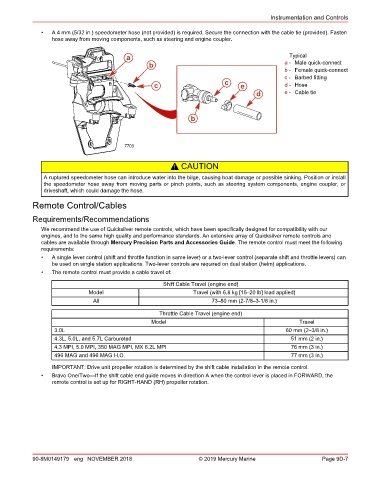
• A 4 mm (5/32 in.) speedometer hose (not provided) is required. Secure the connection with the cable tie (provided). Fasten
hose away from moving components, such as steering and engine coupler.
a Typical
b a - Male quick‑connect
b - Female quick‑connect
c - Barbed fitting
c c e d - Hose
d e - Cable tie
b
7703
! CAUTION
A ruptured speedometer hose can introduce water into the bilge, causing boat damage or possible sinking. Position or install
the speedometer hose away from moving parts or pinch points, such as steering system components, engine coupler, or
driveshaft, which could damage the hose.
Remote Control/Cables
Requirements/Recommendations
We recommend the use of Quicksilver remote controls, which have been specifically designed for compatibility with our
engines, and to the same high quality and performance standards. An extensive array of Quicksilver remote controls and
cables are available through Mercury Precision Parts and Accessories Guide. The remote control must meet the following
requirements:
• A single lever control (shift and throttle function in same lever) or a two‑lever control (separate shift and throttle levers) can
be used on single station applications. Two‑lever controls are required on dual station (helm) applications.
• The remote control must provide a cable travel of:
Shift Cable Travel (engine end)
Model Travel (with 6.8 kg [15–20 lb] load applied)
All 73–80 mm (2‑7/8–3‑1/8 in.)
Throttle Cable Travel (engine end)
Model Travel
3.0L 60 mm (2–3/8 in.)
4.3L, 5.0L, and 5.7L Carbureted 51 mm (2 in.)
4.3 MPI, 5.0 MPI, 350 MAG MPI, MX 6.2L MPI 76 mm (3 in.)
496 MAG and 496 MAG H.O. 77 mm (3 in.)
IMPORTANT: Drive unit propeller rotation is determined by the shift cable installation in the remote control.
• Bravo One/Two—If the shift cable end guide moves in direction A when the control lever is placed in FORWARD, the
remote control is set up for RIGHT‑HAND (RH) propeller rotation.
90-8M0149179 eng NOVEMBER 2018 © 2019 Mercury Marine Page 9D-7