
Page 353 - REPOWER REFERENCE GUIDE (2020)
P. 353
Instrumentation and Controls
Installation
The remote and cables should be installed in accordance with the instructions that accompany them and the instructions in the
power package installation manual. To ensure minimal shift and throttle effort, observe the following information:
• The remote control mounting location must allow for an unobstructed routing of cables within 92 cm (3 ft) of control. This is
necessary because the cables move side to side when the control handle is actuated. Increased shift and throttle effort will
be experienced if cable movement is restricted.
NOTE: Some remote controls can be rotated in 30° increments to improve cable routing.
• Cables must not be fastened to the boat or any other objects within 92 cm (3 ft) of the remote control and engine attaching
points.
• Keep bends to a minimum.
• Route the cables so that they do not have less than an 20 cm (8 in.) radius at all bends.
• Ensure that the cables are not kinked or pinched.
IMPORTANT: Care must also be taken to ensure that the drive unit shift cable is installed properly. Be careful not to pinch
or crush the cable during engine installation. Also, be sure that the cable is properly routed as outlined in Section 8B ‑
Sterndrive Unit Shift Cable Routing.
• Avoid routing the cable in an area where it could be damaged later in the assembly process, such as when a hole is drilled
or a screw is inserted.
• Cable guides and pivot points should be lubricated. Move end guides in and out to evenly distribute the grease.
• Tighten cable attaching nuts until they make contact, then loosen 1/2 turn (until the washer under the nut can be turned
with the fingers). Attaching points must be free to pivot.
Dual Station (Helm) Cable Setup
Dual station (helm) applications only: The remote control cables can be connected in series or in parallel.
When connected in series, the remote control cables from the secondary (top) station are connected to the primary lower
station. The primary station cables are then connected to the engine in the normal manner.
On some applications it may be preferable to connect both sets of cables directly to the engine, using a parallel connection. A
Two Station Throttle/Shift Kit is available for this purpose. Refer to Mercury Precision Parts and Accessories Guide.
d
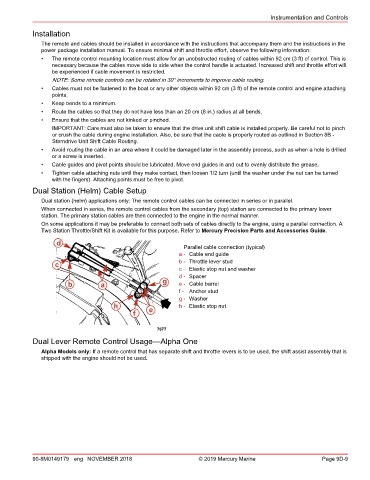
Parallel cable connection (typical)
a - Cable end guide
c b - Throttle lever stud
c - Elastic stop nut and washer
d - Spacer
b a g e - Cable barrel
f - Anchor stud
g - Washer
h e h - Elastic stop nut
f
7677
Dual Lever Remote Control Usage—Alpha One
Alpha Models only: If a remote control that has separate shift and throttle levers is to be used, the shift assist assembly that is
shipped with the engine should not be used.
90-8M0149179 eng NOVEMBER 2018 © 2019 Mercury Marine Page 9D-9