
Page 142 - Installation Manual - GenII DTS
P. 142
DTS System Configuration
Special Tools
Male to Male 10 Pin Adapter 84‑892452A01
Allows connection between CAN P communications cable and Computer
Diagnostic System in applications where a junction box is not used.
4621
Connecting and Starting CDS G3
Connection to the Diagnostic Connector
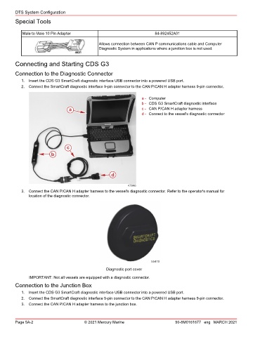
1. Insert the CDS G3 SmartCraft diagnostic interface USB connector into a powered USB port.
2. Connect the SmartCraft diagnostic interface 9‑pin connector to the CAN P/CAN H adapter harness 9‑pin connector.
a - Computer
b - CDS G3 SmartCraft diagnostic interface
a c - CAN P/CAN H adapter harness
d - Connect to the vessel's diagnostic connector
c
b
d
47946
3. Connect the CAN P/CAN H adapter harness to the vessel's diagnostic connector. Refer to the operator's manual for
location of the diagnostic connector.
55479
Diagnostic port cover
IMPORTANT: Not all vessels are equipped with a diagnostic connector.
Connection to the Junction Box
1. Insert the CDS G3 SmartCraft diagnostic interface USB connector into a powered USB port.
2. Connect the SmartCraft diagnostic interface 9‑pin connector to the CAN P/CAN H adapter harness 9‑pin connector.
3. Connect the CAN P/CAN H adapter harness to the junction box.
Page 5A-2 © 2021 Mercury Marine 90-8M0161677 eng MARCH 2021