
Page 143 - Installation Manual - GenII DTS
P. 143
DTS System Configuration
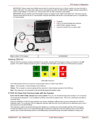
IMPORTANT: Many vessels have difficult access paths to reach the junction box. In these vessels, you may encounter a
yellow CAN cable. The yellow CAN cable can be connected to the CDS G3 CAN P/CAN H adapter harness using either a
male‑to‑male adapter or a junction box. This provides CDS G3 with connection to the system.
IMPORTANT: Ensure that the correct termination resistor is installed on the CAN P and CAN H bus. The buses must be
properly terminated for the tool to communicate. Improper termination will result in communication errors or complete loss
of communication.
a - Computer
b - CDS G3 SmartCraft diagnostic interface
a c - CAN P/CAN H adapter harness
d - Connect to junction box or yellow cable
c
b
d
47946
Male to Male 10 Pin Adapter 84‑892452A01
Starting CDS G3
With the CDS G3 computer correctly connected to the system, and the CDS G3 program running, turn the key to the ON
position. The CAN P indicator should turn green, indicating that CAN traffic exists between the PCM and the computer.
52539
CAN traffic indicators
The CAN indicators will let you know the communication status on CAN P and CAN H.
Green—The computer is communicating on the CAN bus.
Yellow—The computer is communicating with the cable but no data is being received on the CAN bus.
Red—The computer is not connected to the SmartCraft diagnostic interface cable.
If CDS G3 Does Not Communicate with the System
Is the CDS G3 CAN P traffic indicator icon red or yellow? If it is red, the SmartCraft diagnostic interface is not connected,
®
not recognized by Windows , or not configured correctly in the CDS G3 options menu. This is not a CAN issue, but rather a
computer issue.
Improper installation of CDS G3 driver software can result in disabling a USB port from communicating with the CDS G3
diagnostic cable. Try moving the CDS G3 diagnostic interface cable from the current USB port to an alternative port to see if
this resolves the red CAN P/CAN H.
If the indicator is yellow, the SmartCraft diagnostic interface is connected and communicating with the CDS G3 program
through the USB port, but it is not communicating with the CAN bus configured in the port mapping menu in the CDS G3
options menu. Ensure that the key switch is in the ON position and that the proper termination resistance is being used.
90-8M0161677 eng MARCH 2021 © 2021 Mercury Marine Page 5A-3