
Page 105 - Fluid Fitting 2018_extended
P. 105
Fluid Fittings & Fluid Steels
Branding / Logo Usage Guide
The logo(s) should be used as supplied without modification.
Various formats are available upon request to suit all applications.
The following guidelines are to identify the logo makeup and are NOT to be used to recreate the logo except where express
permission has been given to do so.
INDEPENDANT LOGO USAGE
FLUID FITTINGS LOGO
COLOUR - Prefered Option
F
Fittings
The word “FLUID” - Franklin Gothic Heavy
The word “Fittings” - Helvetica Neue Light
The “F” device - Min Round
The colour breakdown for various uses is as follows:
Spot:
Red - PMS 485
Black - Pantone Black
CMYK:
Black
Red
Red
C: 0
C: 0
R: 0
R: 255
M: 100
G: 0
G: 0
M: 0
B: 0
B: 0
Y: 0
Y: 100
K: 100
K: 0 F FLUID RGB: Black
BLACK / GREYSCALE VERSION
F Fittings
EXCELLENCE IN SERVICE
HIGH QUALITY PRODUCTS F FLUID
If necessary the logo can be represented in greyscale. The colour breakdown for various uses is as follows:
Spot:
Black - Pantone Black
Grey - Cool Grey 10
CMYK:
Grey Black RGB:
ASSEMBLY INSTRUCTIONS ACCORDING TO DIN 3859-2 FOR B3 Red Black
C: 0
C: 0
M: 0 M: 0 R: 75 R: 0
Y: 0 Y: 0 G: 75 G: 0
B: 0
K: 70
K: 100
B: 75
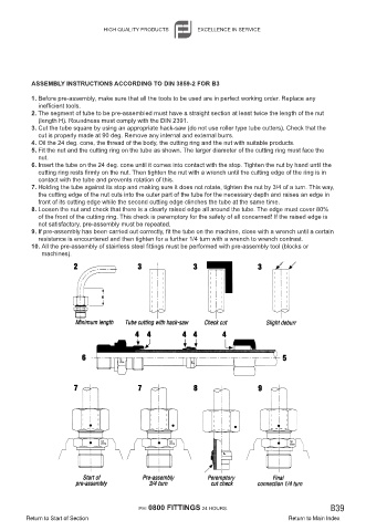
1. Before pre-assembly, make sure that all the tools to be used are in perfect working order. Replace any
inefficient tools.
2. The segment of tube to be pre-assembled must have a straight section at least twice the length of the nut
(length H). Roundness must comply with the DIN 2391.
3. Cut the tube square by using an appropriate hack-saw (do not use roller type tube cutters). Check that the
cut is properly made at 90 deg. Remove any internal and external burrs.
4. Oil the 24 deg. cone, the thread of the body, the cutting ring and the nut with suitable products.
5. Fit the nut and the cutting ring on the tube as shown. The larger diameter of the cutting ring must face the
nut.
6. Insert the tube on the 24 deg. cone until it comes into contact with the stop. Tighten the nut by hand until the
cutting ring rests firmly on the nut. Then tighten the nut with a wrench until the cutting edge of the ring is in
contact with the tube and prevents rotation of this.
7. Holding the tube against its stop and making sure it does not rotate, tighten the nut by 3/4 of a turn. This way,
the cutting edge of the nut cuts into the outer part of the tube for the necessary depth and raises an edge in
front of its cutting edge while the second cutting edge clinches the tube at the same time.
8. Loosen the nut and check that there is a clearly raised edge all around the tube. The edge must cover 80%
of the front of the cutting ring. This check is peremptory for the safety of all concerned! If the raised edge is
not satisfactory, pre-assembly must be repeated.
9. If pre-assembly has been carried out correctly, fit the tube on the machine, close with a wrench until a certain
resistance is encountered and then tighten for a further 1/4 turn with a wrench to wrench contrast.
10. All the pre-assembly of stainless steel fittings must be performed with pre-assembly tool (blocks or
machines).
PH: 0800 FITTINGS 24 HOURS. B39
Return to Start of Section Return to Main Index