
Page 337 - Fluid Fitting 2018_extended
P. 337
HIGH QUALITY PRODUCTS EXCELLENCE IN SERVICE
ASSEMBLY INSTRUCTIONS
STANDARD TWO EDGE CUTTING RING CONT.
b). Assembly in Coupling Body.
Direct assembly in a coupling body is carried out similarly to pre-assembly in a fixture, except that the
final assembly is completed in the same process. The marked nut is finally tightened approx. 1 1/4 to 1
1/2 turns so that the coupling is completely assembled. Control the cutting ring and bead as described
in a). “In Pre-Assembly Fixture”.
Caution: This form of assembly is not recommended for Stainless Steel fittings.
Note:
For the pre-assembly of couplings only use
hardened fixtures.
With use, even hardened fixtures are subject to
wear, therefore, periodically inspect the accuracy
and tolerance of the taper.
By wear and non-confirmity replace the fixture.
The assembly of a coupling can be eased by loosening the coupling nut each time the tightening torque
becomes excessive.
In the case of large diameter tubes the assembly can be considerably eased by releasing the coupling
nut and retreating the contact surfaces with assembly grease.
The high strength of AISI 316 ti material presents a considerably higher cutting ring resistance than
carbon steel, and therefore results in a less heavy bead build up than is typical with carbon steel.
An special oxygen- compatible assembly grease is available on request for use with couplings to be
used in oxygen based applications.
ASSEMBLY:
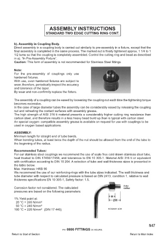
Minimum length for straight end of tube bends.
When bending tubes, at least twice the depth of the nut should be allowed from the end of the tube to
the beginning of the radius.
Recommended Tubes:
For our stainless steel couplings we recommend the use of scale free cold drawn stainless steel tube,
heat treated to DIN 17456/17458, and tolerances to EN 10 305-1. Material AISI 316 ti or equivalent
with certification according to DIN 10 204. A selection of tube and wall thickness sizes is presented in
the table below.
Max. Hardness: HRB 90
We recommend the use of our reinforcing-rings with the tube sizes indicated. The wall thickness and
tube diameter with respect to calculated pressure is based on DIN 2413, condition 1, relative to wall
thickness specifications EN 10 305-1, Safety factor: 1.5.
Corrosion factor not considered. The calculated
pressures are based on the following parameters:
1% Yield point at:
20 °C = 265 N/mm²
50 °C = 240 N/mm²
100 °C = 220 N/mm² (DIN 17 440)
PH: 0800 FITTINGS 24 HOURS. N47
viii
PH: 0800 FITTINGS 24 HOURS.
Return to Start of Section Return to Main Index