
Page 17 - C:\Users\trainee\AppData\Local\Temp\msoEAA3.tmp
P. 17
Document Title
Fundamentals of Stress and Vibration 2. Engineering Mechanics Chapter
[A Practical guide for aspiring Designers / Analysts]
ȋʹǤͳͺȌ
ȏ ʹǤͳʹȐ
1
2
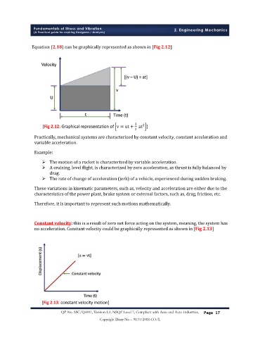
[Fig 2.12: Graphical representation of v = ut + at ]
2
Practically, mechanical systems are characterized by constant velocity, constant acceleration and
variable acceleration.
Example:
Ø The motion of a rocket is characterized by variable acceleration.
Ø A cruising, level flight, is characterized by zero acceleration, as thrust is fully balanced by
drag.
Ø The rate of change of acceleration (jerk) of a vehicle, experienced during sudden braking.
These variations in kinematic parameters, such as, velocity and acceleration are either due to the
characteristics of the power plant, brake system or external factors, such as, drag, friction, etc.
Therefore, it is important to represent such motions mathematically.
Constant velocity: this is a result of zero net force acting on the system, meaning, the system has
no acceleration. Constant velocity could be graphically represented as shown in [Fig 2.13]
[Fig 2.13: constant velocity motion]
QP No. SSC/Q4401, Version 1.0, NSQF Level 7, Compliant with Aero and Auto Industries, P
Page 17 age 17
Copyright Diary No – 9119/2018-CO/L