Page 370 - Clinical Application of Mechanical Ventilation
P. 370

336    Chapter 11


                                            of the P ALV  is developed in the second half of inspiration (P ALV  5 25% 3 40 cm
                                            H O 5 10 cm H O, or P ALV  5 0.125 L/0.0125 L/cm H O 5 10 cm H O). Thus,
                                                          2
                                             2
                                                                                                         2
                                                                                            2
                                            any point along the P ALV  curve can be predicted and plotted by calculating the
                                            volume delivered per time provided that total C  is known. This calculation for
                                                                                      LT
                                            DRFW also applies to CFW.
                                             In the second example (Figure 11-17), peak flow is maintained at 60 L/min,
                                            but V  is doubled [1/2(60 L/min]/60s/min 3 2s 5 1 L], which increases T  to
                                                 T
                                                                                                               I
                                            2 sec. As a result of doubling V , peak P ALV  is doubled (P ALV  5 1.0 L/0/0125 L/cm
                                                                      T
                                            H O 5 80 cm H O). Note that the initial flow-resistive pressure is sustained in the
                                                          2
                                             2
                                            second pressure waveform since the initial flow has not changed.
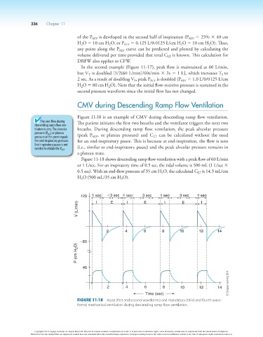
                                            CMV during Descending Ramp Flow Ventilation
                                            Figure 11-18 is an example of CMV during descending ramp flow ventilation.
                          The end-flow during   The patient initiates the first two breaths and the ventilator triggers the next two
                        descending ramp flow ven-
                        tilation is zero. The alveolar   breaths.  During  descending  ramp  flow  ventilation,  the  peak  alveolar  pressure
                        pressure (P ALV ) or plateau   (peak  P  ,  or  plateau  pressure)  and  C   can  be  calculated  without  the  need
                        pressure at this point equals   ALV                    LT
                        the end-inspiratory pressure.   for an end-inspiratory pause. This is because at end-inspiration, the flow is zero
                        End-inspiratory pause is not
                        needed to obtain the P ALV .  (i.e., similar to end-inspiratory pause) and the peak alveolar pressure remains in
                                            a plateau state.
                                             Figure 11-18 shows descending ramp flow ventilation with a peak flow of 60 L/min
                                            or 1 L/sec. For an inspiratory time of 0.5 sec, the tidal volume is 500 mL (1 L/sec 3
                                            0.5 sec). With an end-flow pressure of 35 cm H O, the calculated C  is 14.3 mL/cm
                                                                                                    LT
                                                                                   2
                                            H O (500 mL/35 cm H O).
                                                                2
                                             2
                                             120  1 sec  ,3 sec  1 sec    3 sec   1 sec    3 sec    1 sec
                                                           E
                                                                   I
                                                    I
                                                                           E
                                                                                                     I
                                                                                    I
                                                                                            E
                                            V (L/min)
                                                         2        4        6       8       10       12       14


                                             260
                                           P (cm H 2 O)


                                              40
                                                                                                                  © Cengage Learning 2014


                                                         2        4        6       8        10      12       14
                                                                           Time (sec)
                                            Figure 11-18  Assist (first and second waveforms) and mandatory (third and fourth wave-
                                            forms) mechanical ventilation during descending ramp flow ventilation.


                        Copyright 2013 Cengage Learning. All Rights Reserved. May not be copied, scanned, or duplicated, in whole or in part. Due to electronic rights, some third party content may be suppressed from the eBook and/or eChapter(s).
                      Editorial review has deemed that any suppressed content does not materially affect the overall learning experience. Cengage Learning reserves the right to remove additional content at any time if subsequent rights restrictions require it.
   365   366   367   368   369   370   371   372   373   374   375