
Page 37 - E BOOK ENGINE MECHANICAL M2
P. 37
5. SERVICE POINTS OF 4B1 ENGINE COMPONENT
3. PISTON AND CONNECTING ROD
<Piston Replacement>
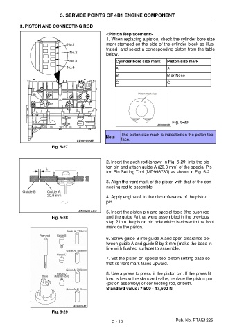
1. When replacing a piston, check the cylinder bore size
mark stamped on the side of the cylinder block as illus-
trated and select a corresponding piston from the table
below.
Cylinder bore size mark Piston size mark
A A
B B or None
C C
Fig. 5-20
The piston size mark is indicated on the piston top
Note
face.
Fig. 5-27
2. Insert the push rod (shown in Fig. 5-29) into the pis-
ton pin and attach guide A (20.9 mm) of the special Pis-
ton Pin Setting Tool (MD998780) as shown in Fig. 5-21.
3. Align the front mark of the piston with that of the con-
necting rod to assemble.
4. Apply engine oil to the circumference of the piston
pin.
5. Insert the piston pin and special tools (the push rod
Fig. 5-28 and the guide A) that were assembled in the previous
step 2 into the piston pin hole which is closer to the front
mark on the piston.
6. Screw guide B into guide A and open clearance be-
tween guide A and guide B by 3 mm (make the base in
line with flushed surface) to assemble.
7. Set the piston on special tool piston setting base so
that its front mark faces upward.
8. Use a press to press fit the piston pin. If the press fit
load is below the standard value, replace the piston pin
(piston assembly) or connecting rod, or both.
Standard value: 7,500 - 17,500 N
Fig. 5-29
5 - 10 Pub. No. PTAE1225