
Page 299 - Robot Design Handbook ROBOCON Malaysia 2019
P. 299
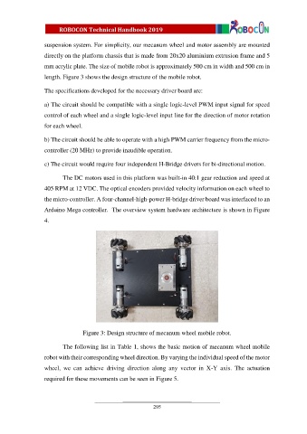
suspension system. For simplicity, our mecanum wheel and motor assembly are mounted

                  directly on the platform chassis that is made from 20x20 aluminium extrusion frame and 5
                  mm acrylic plate. The size of mobile robot is approximately 500 cm in width and 500 cm in

                  length. Figure 3 shows the design structure of the mobile robot.

                  The specifications developed for the necessary driver board are:

                  a) The circuit should be compatible with a single logic-level PWM input signal for speed

                  control of each wheel and a single logic-level input line for the direction of motor rotation

                  for each wheel.

                  b) The circuit should be able to operate with a high PWM carrier frequency from the micro-

                  controller (20 MHz) to provide inaudible operation.

                  c) The circuit would require four independent H-Bridge drivers for bi-directional motion.

                         The DC motors used in this platform was built-in 40:1 gear reduction and speed at

                  405 RPM at 12 VDC. The optical encoders provided velocity information on each wheel to
                  the micro-controller. A four-channel-high-power H-bridge driver board was interfaced to an

                  Arduino Mega controller.  The overview system hardware architecture is shown in Figure

                  4.


                                 Figure 3: Design structure of mecanum wheel mobile robot.

                         The following list in Table 1, shows the basic motion of mecanum wheel mobile

                  robot with their corresponding wheel direction. By varying the individual speed of the motor
                  wheel,  we  can  achieve  driving  direction  along  any  vector  in  X-Y  axis.  The  actuation

                  required for these movements can be seen in Figure 5.


                                                            295