
Page 87 - Robot Design Handbook ROBOCON Malaysia 2019
P. 87
2.3.2 Messenger Robot 2 (MR2)
START
LDR Module
(Arduino A0)
Arduino 1 NO
pinMode (relay, OUTPUT)
pinMode (LDR, INPUT)
AnalogValue =
analogRead(A0)
YES
Relay Module
#define Relay 10
END
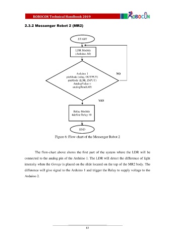
Figure 6: Flow-chart of the Messenger Robot 2
The flow-chart above shows the first part of the system where the LDR will be
connected to the analog pin of the Arduino 1. The LDR will detect the difference of light
intensity when the Gerege is placed on the slide located on the top of the MR2 body. The
difference will give signal to the Arduino 1 and trigger the Relay to supply voltage to the
Arduino 2.
83