
Page 191 - The City and Guilds Textbook: Plumbing Book 1 for the Level 3 Apprenticeship (9189), Level 2 Technical Certificate (8202) and Level 2 Diploma (6035)
P. 191
Chapter 3 Scientific principles
There are three classes of lever, as follows.
l First class lever: a simple see-saw arrangement where the long arm
(force effort) is proportional to the short arm (load). Examples of this
are:
l the lever arm of a float-operated valve
l claw hammer
l water pump pliers (double lever). F
W
l Second class lever: a variation on the first class lever. Examples of this
are: p Figure 3.23 First class lever
l wheelbarrow
l crowbar.
l Third class lever: examples of this are:
l the human arm
l tools, such as a hoe or scythe
l spades and shovels.
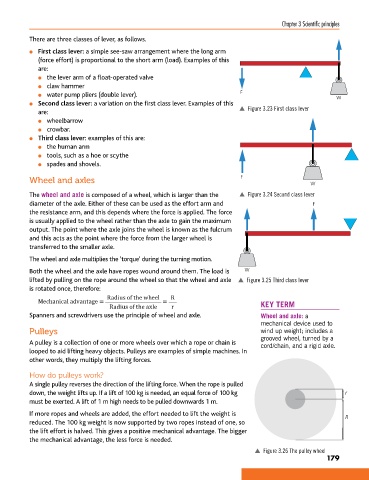
Wheel and axles F W
The wheel and axle is composed of a wheel, which is larger than the p Figure 3.24 Second class lever
diameter of the axle. Either of these can be used as the effort arm and F
the resistance arm, and this depends where the force is applied. The force
is usually applied to the wheel rather than the axle to gain the maximum
output. The point where the axle joins the wheel is known as the fulcrum
and this acts as the point where the force from the larger wheel is
transferred to the smaller axle.
The wheel and axle multiplies the ‘torque’ during the turning motion.
Both the wheel and the axle have ropes wound around them. The load is W
lifted by pulling on the rope around the wheel so that the wheel and axle p Figure 3.25 Third class lever
is rotated once, therefore:
Radius of the wheel R
Mechanical advantage = = KEY TERM
Radius of the axle r
Spanners and screwdrivers use the principle of wheel and axle. Wheel and axle: a
mechanical device used to
Pulleys wind up weight; includes a
grooved wheel, turned by a
A pulley is a collection of one or more wheels over which a rope or chain is cord/chain, and a rigid axle.
looped to aid lifting heavy objects. Pulleys are examples of simple machines. In
other words, they multiply the lifting forces.
How do pulleys work?
A single pulley reverses the direction of the lifting force. When the rope is pulled
down, the weight lifts up. If a lift of 100 kg is needed, an equal force of 100 kg r
must be exerted. A lift of 1 m high needs to be pulled downwards 1 m.
If more ropes and wheels are added, the effort needed to lift the weight is R
reduced. The 100 kg weight is now supported by two ropes instead of one, so
the lift effort is halved. This gives a positive mechanical advantage. The bigger
the mechanical advantage, the less force is needed.
p Figure 3.26 The pulley wheel
179
9781510416482.indb 179 29/03/19 8:55 PM