
Page 336 - The City and Guilds Textbook: Plumbing Book 1 for the Level 3 Apprenticeship (9189), Level 2 Technical Certificate (8202) and Level 2 Diploma (6035)
P. 336
The City & Guilds Textbook: Plumbing Book 1
Preparation, planning and positioning of pipes
The installation of cold water systems needs to comply with the Water Supply
(Water Fittings) Regulations and we must always consider the recommendations
of BS EN 806 and BS 8558. The manufacturer’s instructions have to be
followed with regard to the appliances installed and materials used.
The installation procedures will vary depending on the property. For instance,
the methods used on new buildings will differ from those in an occupied
dwelling where the customer’s possessions will need to be taken into account.
Irrespective of the property type, pipework runs need to be planned carefully.
It is advisable to avoid positions where frost and heat could cause a problem,
such as outside walls, in cellars and unheated roof spaces. Wherever possible,
pipework should be positioned out of sight and boxed in where appropriate. It
should be remembered, however, that pipework should not be buried in walls
INDUSTRY TIP or floors unless provision can be made to make it accessible.
Notching and drilling of joists Pipes in suspended timber floors
should be done carefully, Pipes have been installed in timber floors for many years. Notching or drilling
taking care to follow the of joists should not be carried out in joists or rafters 100 mm deep or less.
recommendations mentioned
in Chapter 2, Common Notches should not be too tight for the pipes or creaking and ‘ticking’ noises
processes and techniques, may become a problem as the pipes expand and contract. Pipes in notches
page 121. should be covered with joist clips to prevent excessive movement, and
floorboards should be screwed (not nailed) when they are repositioned.
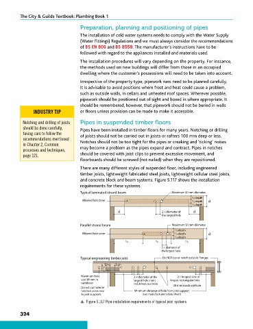
There are many different styles of suspended floor, including engineered
timber joists, lightweight fabricated steel joists, lightweight cellular steel joists,
and concrete block and beam systems. Figure 5.117 shows the installation
requirements for these systems.
Typical laminated strand beam Maximum 50 mm diameter
1 / 3 depth
Allowed hole zone 1 / 3 depth d
1 / 3 depth
d 2 × diameter of d
the largest hole
Parallel strand beam Maximum 50 mm diameter
1 / 3 depth
Allowed hole zone 1 / 3 depth d
1 / 3 depth
1 / 3 1 / 3 1 / 3
2 × diameter of
the largest hole
Typical engineering timber joist Do NOT cut or notch out joist flanges
150 mm 150 mm 150 mm
Maximum hole 2 × diameter of the 2 × longest side of
size 38 mm in largest hole (mm) largest rectangular hole
cantilever incl. knock out hole
Do not cut holes in 38 mm knock out hole
hatched areas near Minimum distance of hole from joist support
to joist supports (see manufacturer's data sheet)
p Figure 5.117 Pipe installation requirements of typical joist systems
324
9781510416482.indb 324 29/03/19 8:59 PM