Page 134 - APPLIED PROCESS DESIGN FOR CHEMICAL AND PETROCHEMICAL PLANTS, Volume 1, 3rd Edition
P. 134

118                       Applied Process Design for Chemical  and Petrochemical  Plants

            (text continued from page  115)                          Flow of gases and vapors  ( compressible fluids)  through
                    q  =  cu ft/sec at flowing conditions  (Figure 2-37)  Coef-   nozzles and orifices.  (For flow field importance see Refer-
                        ficient from Reference  [22]  for liquids discharge   ences  [31]). From  [3]:

                    r0  = critical  pressure  ratio for compressible flow,  =
                        P'2/P'1                                            ,   2g ( l 44)6P
                                                                     q  = YC  A   '     ,  cu ft I  sec
                                                                                  p
                                                                         (at flowing conditions)               (2-  48)

                                                                    Y =  net expansion factor from Figures 2-38A or 2-38B
                                                                   llP  =  differential  pressure  (equal  Lo inlet gauge pressure when
                       .14                                              discharging to atmosphere)
                          ................  .....                   p  = weight density of fluid, lbs/cu ft at flowing conditions
                                   -..............  r--.....        A  =  cross section of orifice or nozzle, sq ft
                       .II                                         C' = flow coefficient from Figures 2-38A or 2-38B
                         <,  ,....__         .............  ...  r----.J.  ...
                                                ........._
                               r-,......               !  i
                    ---·'°   ........   .............   +-,        or,  W  =  1891  Yd 1  C  ,   I =-, lbs/hr   (2-  95)
                                                                                      !lP
                                                                                  2
                     Q.
                    .....   !'-....          ........._   t-r  "                     I  vi
                    ..........
                     Q.   ............  �   -..  .............  .......   """<
                     II  .!ol  ............   r-;   -..............   /�  "   where  d, = internal diameter of orifice,  in
                     ......   ....   ....  ........._   ...........   i""---....   .......   V1  =  specific volume of  fluid, cu ft/lb
                                ...........
                         �   .............  �  r-;  ...........  <,  1   I  I   ..
                       . 16        r-,   -......  ............ -   i""'-<.,,
                         �  �  <;     r-;              ..                            ,  /ilP  P/
                                                        •
                                                                                  O  f- : -,
                             ..........   ..........                   ,          2
                               :::::::: �  r-.......   <,  �       or,  q  =  11. 30 Yd  C   cu ft/sec
                                                    ___.....
                       .!><                        ....                               I  T1  Sg
                                     """"R  �  �    v'  II                at 14. 7 psia and  60° F             (2-  96)
                                     ---            L----"_:
                                             �  �
                                                 .....,..,  _,
                       .ail                                        where  Sg  =  Sp Gr gas relative Lo air,  =  mo! wt,  gas/29
                                                                                               0
                        us     I.I    l.lS   l4    I'S                   Ti= absolute temperature,  R
                                    k=Cp/C�                             P' 1  =  pressure, psi  abs
                   P' = psia                                       Procedure
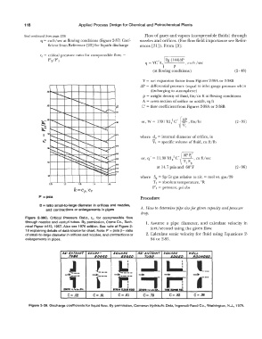
                    B = ratio small-to-large diameter in orifices and nozzles,   A.  How to determine fripe size for giuen capacity  and pressure
                       and  contractions or enlargements in pipes
                                                                   drop.
             Figure  2-38C.  Critical  Pressure  Ratio,  re,  for  compressible  flow
             through  nozzles and venturi  tubes.  By permission,  Crane Co.,  Tech-   1. Assume  a  pipe  diameter,  and  calculate  velocity  in
             nical Paper #410,  1957.  Also see 1976 edition.  See note at Figure 2-   feet/  second using the given flow.
             18 explaining details of data source for chart.  Note:  P' =  psia �= ratio
             of small-to-large diameter in orifices and nozzles, and contractions or   2.  Calculate sonic velocity for fluid using Equations  2-
             enlargements in pipes.                                    84 or 2-85.
                                                                                             ,
                              lt6·INUANT  SHARP-      $QVAltE     RE·ENTRANT  5QtlAllE    WELL
                                 TV61        IDtilD       IDG£D    _J  __  w  __           ROVNDED
                                                                     TV/JI
                                                                                 EDGED
                                              !  __
                                 J
                               -,=          1--       -,,-  -,--              .......      -+   ___
                                                        �-
                                                                               n-  i---
                                                                  �
                               1DCrJ1 1/•t.tDIA.      ITIIIAM  Cl.Ult lll!U   UIICT!I • 'L-tl'a DIA.   Tlllt IUlnl Fllt
                                  1
                                 C= .52      C= .61     C= .61      C= .73      C= .82      C= .98

               Figure 2-39.  Discharge coefficients for liquid flow.  By permission, Cameron Hydraulic Data,  Ingersoll-Rand Co., Washington,  N.J., 1979.
   129   130   131   132   133   134   135   136   137   138   139