Page 149 - APPLIED PROCESS DESIGN FOR CHEMICAL AND PETROCHEMICAL PLANTS, Volume 1, 3rd Edition
P. 149

Fluid Flow                                            133


                               Table 2-21                          The  suction  pressure  required  at  the  vacuum pump  (in
            Criteria for Sizing Connecting Lines in Vacuum Service   absolute pressure)  is the actual  process equipment operat-
                                                                 ing pressure minus  the  pressure  loss  between  the  process
           Vacuum pump                 Assumed flow velocity,  ft/  s
                                                                 equipment and the source of the vacuum. Note that absolute
           Steam.jet:                                           pressures  must  be  used  for  these  determinations  and  not
             System  pressure,  torr                             gauge pressures.  Also keep in mind that the absolute pres-
              0.5-5                              300             sure at the vacuum pump must always be a lower absolute
              5-25                               250
              25-150                             200             pressure  than  the absolute pressure at the process.
              150--760                           150
           Liquid ring pump:                                    Pipe Sizing for Non-Newtonian Flow
             Single-stage"                       100
             Two-stage                           150               Non-Newtonian  fluids  vary  significantly  in  their prop-
           Rotary piston:                                        erties that control flow and pressure loss during flow from
             Single-stage                         50             the properties  of Newtonian  fluids.  The key factors influ-
             Two-stage                            25             encing non-Newtonian fluids  are  their shear thinning  or
           Rotary vane.j                                         thickening characteristics and time dependency of viscos-
             Single-stage                        200             ity on the stress in the fluid.
             Two-stage                           400               Most conventional chemical  and petrochemical  plants
           Rotary blowers:                                       do  not process  many,  if any,  non-Newtonian fluids.  How-
            Atmospheric discharge                 50             ever,  polymers,  grease,  heavy  oils,  cellulose  compounds,
             Discharging to backing pump         100
                                                                 paints, fine chalk suspensions in water,  some asphalts, and
           �Assumes  the  pump  features  dual  inlet connections  and  that  an  inlet   other  materials  do  exhibit  one  type  or  another  of the
            manifold will be used.                               characteristics of non-Newtonians,  classified as:
           +Based on  rough vacuum process  pumps.  Use  25  ft/s  for high  vacuum
            pumps.
            By permission, Ryans.]. L. and Roper,  D. L., Process Vacuum System Design   • Bingham plastics
            and  Operation,  McGraw-Hill  Book Co.  Inc.,  1986  [18].   • Dilatant
                                                                   • Pseudoplastic
                                                                   • Yield pseudoplastics
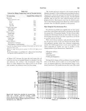
           of Figure  2-47,  increase  the  pipe  size and repeat the  cal-
           culations until  an  acceptable balance is obtained.  For ini-   Solving these classes of flow problems requires specific
           tial  estimates,  the  authors  [ 18]  recommend  using  0.6   data on  the fluid, which  is  often  not in  the  public  litera-
           times  the value  obtained from  Figure  2-4  7  for an  accept-   ture,  or requires  laboratory  determinations  using a  rota-
           able pressure loss between vessel  and the pump.      tional viscometer.  The results do not allow use of the usual


                                                    1000
                                                      8
                                                      6

                                                       4
                                                       3                           -  ...   -�
                                                   ..   2                                    -   -Wui

                                                  �                                      -�
                                                                                                  ci  J  I �   .
                                                   i                                        �i---...  es1gn  as,s  ""'"'�
                                                  ·g  100
                                                  "ii   8                      .
                                                                                                  Miniin�rri
                                                  >   6                                      �   � .......
                                                                                                           ..---
                                                      4                                                     -�
                                                      3
           Figure  2-46.  Typical  flow  velocities  for  vacuum  lines.   2   .
           Note:  1  torr  =  1.33 mb  =  133.3 Pa.  1.0 ft/sec  =  0.3048
           rn/sec,  By  permission,  Ryans,  J.  L.  and  Roper,  D.  L.,   10
           Process Vacuum System Design &  Operation,  McGraw-   1   2   3  466789   2   3  456789100   2   3  4  567891000
           Hill Book Co.,  Inc.,  1986 [18].                               Pressure, torr
   144   145   146   147   148   149   150   151   152   153   154