
Page 280 - APPLIED PROCESS DESIGN FOR CHEMICAL AND PETROCHEMICAL PLANTS, Volume 1, 3rd Edition
P. 280
250 Applied Process Design for Chemical and Petrochemical Plants
liquids and systems with very bad fouling conditions.
Table 4-11 indicates the effect of disengaging height on
the allowable k value. Similar relations should hold for
other mesh densities.
Low Density or
Velocity Limitations �100 , High Through-Put Mesh,
c
� ��
Cl)
Very low velocities will allow particles to drift through - Standard Mesh- \
� 80
the mesh and be carried out with the leaving vapor. Also,
very high velocities will carry liquid to the top of the LL.I
c 60
mesh, establish a "flooding" condition, and then re- Cl>
(.)
entrain the liquid from the surface of the mesh. For most cf 40
situations very good performance can be expected for all - Data for Air-Water
System
velocities from 30% to 100% of the optimum allowable �20 Atmospheric Pressure -
Cl>
design velocity. The minimum allowable safe design veloc- 3: I I I I
ity is 10 percent of the value calculated by the equation. 2 4 6 8 10 12 14 16 18
The flooding velocity of the mesh is usually about 120 per- Superficia I Vapor Velocity, Feet/Second
cent to 140 percent of the maximum allowable velocity.
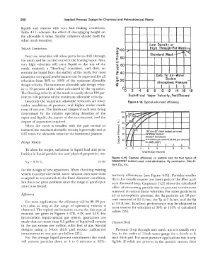
Generally the maximum allowable velocities are lower Figure 4-18. Typical wire mesh efficiency.
under conditions of pressure, and higher under condi-
tions of vacuum. The limits and ranges of each area being
determined by the relative operating densities of the 100
vapor and liquid, the nature of the entrainment, and the 90
degree of separation required. � BO
When the mesh is installed with the pad vertical or >,
o
c
inclined, the maximum allowable velocity is generally used at ·c:; 70 153 mm (6") thick except as noted
Q)
0.67 times the allowable value for the horizontal position. i: 60 -----+--Air/Water System
UJ
� Ambient Conditions
::,
1i 50 ..,...-..,1---+-- 2.4 meters per second (8 feet per second
"'
Design Velocity o K=.085 (.280")
To allow for surges, variations in liquid load and pecu- 2 3 4 5 6 7 8 9 10
liarities in liquid particle size and physical properties, use: Droplet Size (microns)
Figure 4-19. Capture efficiency vs particle size for four types of
V 0 = 0.75 V,, ( 4-48) DEMISTER® knitted mesh mist eliminators. By permission, Otto H.
York Co., Inc.
for the design of new separators. When checking existing
vessels to accept wire mesh, some variation may have to be recovery efficiencies [see Figure 4-19]. Particles smaller
accepted to accommodate the fixed diameter condition, than this usually require two mesh pads or the fiber pack
but this is no great problem since the range of good oper- style discussed later. Carpenter [ 4,5] shows the calculated
ation is so broad. effect of decreasing particle size on percent entrainment
removed at various linear velocities. For water particles in
Efficiency air at atmospheric pressure, the 8µ particles are 99 per-
cent removed at 3.5 ft/sec, the 7µ al 5 ft/sec, and the 6µ
For most applications the efficiency will be 98-99 per- at 6.8 ft/sec. Excellent performance may be obtained in
cent plus as long as the range of operating velocity is most systems for velocities of 30% to 110% of calculated
observed. The typical performance curves for this type of values [35].
material are given in Figures 4-l 7B, 4-18, and 4-19. For
hydrocarbon liquid-natural gas system, guarantees are
made that not more than 0.1 gallon of liquid will remain Pressure Drop
in the gas stream per million cubic feet of gas. Special
designs using a 3-foot thick pad reduce radioactive Pressure drop through wire mesh units is usually very
entrainment to one part per billion [21]. low, in the order of I-inch water gauge for a 4-inch or 6-
For the average liquid process entrainment the mesh inch thick pad. For most pressure applications this is neg-
will remove particles down to 4 to 6 microns al 95%+ ligible. If solids are present in the particle stream, then