
Page 282 - APPLIED PROCESS DESIGN FOR CHEMICAL AND PETROCHEMICAL PLANTS, Volume 1, 3rd Edition
P. 282
252 Applied Process Design for Chemical and Petrochemical Plants
keep velocities low and not to force or carry the liquid
through to the downstream side of the mesh.
Example 4-5: Wire Mesh Entrainment Separator
Design a flash drum to separate liquid ethylene
entrainment for the following conditions:
Volume of vapor= 465 CFM @-l l0°F and 35 psig
Density of vapor= 0.30 lb/cu ft
Density of liquid ethylene = 33 lb/ cu ft
Allowable velocity for wire mesh:
Va=k¥
I P v
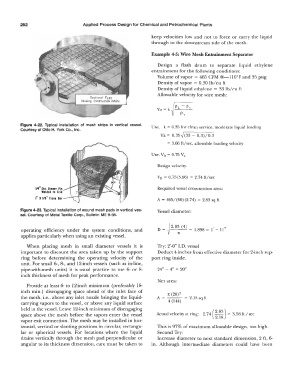
Figure 4-22. Typical installation of mesh strips in vertical vessel. Use, k = 0.35 for clean service, moderate liquid loading
Courtesy of Otto H. York Co., Inc.
Va= 0.35 � (33 - 0.3)/0.3
= 3.66 ft/sec, allowable loading velocity
Use, Vo= 0.75 Va
Design velocity:
V0 = 0.75(3.66) = 2.74 ft/sec
1/4" Dia. Skewtr Pin Required vessel cross-section area:
Welded to Grid
r" X 1/8" Cross Bar A= 465/ (60) (2.74) = 2.83 sq ft
Figure 4-23. Typical installation of wound mesh pads in vertical ves- Vessel diameter:
sel. Courtesy of Metal Textile Corp., Bulletin ME 9-58.
� 2·8 � 4
operating efficiency under the system conditions, and D = ( ) = 1.898 = I' -11"
applies particularly when using an existing vessel.
When placing mesh in small diameter vessels it is Try: 2'-0" I.D. vessel
important to discount the area taken up by the support Deduct 4 inches from effective diameter for 2-inch sup-
ring before determining the operating velocity of the port ring inside.
unit. For small 6-, 8-, and 12-inch vessels (such as in-line,
pipe-with-mesh units) it is usual practice to use 6- or 8- 24" - 4" = 20"
inch thickness of mesh for peak performance.
Net area:
Provide at least 6- to 12-inch minimum (preferably 18-
inch min.) disengaging space ahead of the inlet face of 7t (20) 2
the mesh, i.e., above any inlet nozzle bringing the liquid- A= =2.18sqft
carrying vapors to the vessel, or above any liquid surface 4 (144)
held in the vessel. Leave 12-inch minimum of disengaging ( 2·83)
space above the mesh before the vapors enter the vessel Actual velocity at ring: 2. 74 2.18 = 3.56 ft I sec
vapor exit connection. The mesh may be installed in hor-
izontal, vertical or slanting positions in circular, rectangu- This is 97% of maximum allowable design, too high.
lar or spherical vessels. For locations where the liquid Second Try:
drains vertically through the mesh pad perpendicular or Increase diameter to next standard dimension, 2 ft, 6-
angular to its thickness dimension, care must be taken to in. Although intermediate diameters could have been