
Page 281 - APPLIED PROCESS DESIGN FOR CHEMICAL AND PETROCHEMICAL PLANTS, Volume 1, 3rd Edition
P. 281
Mechanical Separations 251
solids build-up can become appreciable, and is usually the special situations have been placed at an angle to the hor-
guide or indicator for cleaning of the mesh. A 12-inch pad izontal, but these usually accumulate liquid in the lower
may require a 3-inch water drop. Figures 4-20 and 4-21 portion of the mesh. Since the material is not self-sup-
present the range of expected pressure drops for a spread porting in sizes much over 12 inches in diameter, it
of 3 to 1600 lb/hr-ft for liquid rates. Although this is for requires support bars at the point of location in the vessel.
2
air-water system at atmospheric pressure it will not vary In most instances it is wise to also install hold-down bars
much unless the physical properties of the vapor and liq- across the top of the mesh in accordance with manufac-
uid deviate appreciably from this system, in which case the turers' instructions as the material will tend to blow
general Fanning equation can be used to approximate upward with a sudden surge or pulsation of vapor in the
the pressure drop under the new conditions. Approxi- system. Many early installations made without the bars on
mate values based upon air-water tests suggest these rela- top were soon found ineffective due to blowout holes, and
tions [3]: wire particles were found in pipe and equipment down-
For the standard weave, 4 inches thick: stream of the installation. Figures 4-22 and 4-23 show a
typical installation arrangement in a vertical vessel. The
t.p = 0.2 V 02 p,, in. water ( 4-49) mesh is wired to the bottom support bars and the hold-
down on top.
For the low density weave (high through-put), 6 inches A few typical arrangements of mesh in vessels of various
thick: configurations are shown in Figure 4-24.
Note that in some units of Figure 4-24 the mesh diam-
( 4-50) eter is smaller than the vessel. This is necessary for best
Installation
5.o...------------.------.---,--..---,
The knitted mesh separator unit may be placed in a
pipe in which case a round flat rolled unit is usually used, 4.0.--------+----+---�-+-----
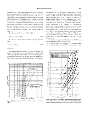
or it may be placed in a conventional vessel. Although the 3.0 .A. 3 GPM/Sq.Ft. (.12m"lminlm 2) t--+--+--+-------i
.A.
• 2 GPM/Sq.Ft. (.08m !minlm
2)
2
vessel may be horizontal or vertical, the mesh must always 2 0 • 1 GPM/Sq.Ft. (.04m /min!m 2)
3
.
be in a horizontal plane for best drainage. Some units in A
I
(5'1.01---------+-----+;=---l-4j----,i----J
10 ��.Bt--------t--�---rf--_.'!'-J'lill,,-,H-4 ..... �
� .71---------+----rl---+---f-++,f--,...--¥1-----1
"
� .5i----------t---,f--t---r--;--;:ft--,lll-,F---;
Entroinmut Load
lb1./(h<li1q. ft. Crou·Stclion) � .41---------+�_,_--��-=;:=.l,L--#---l-l--�
Appro1imate 3 o�
� .31------::...._--+�---r-lr"---.11.£--hl--l-t---f
1600
;:;
<,
I
I c- '/ I .21----------A---l'-4�+--"-l--�---l--+---#-l
"'
Q)
s:
o
' /. � v £ �----1---+----I
a: 0.1 >--------++....,____,,__
I L "� 0
� .OBt---------...<t-F----,.._+illl--
il.O I I ...., .... -t---1--t----i
L ,..... r-; I UJ
§.06t---------+---#--#+-il-----l---+----f
io.1 '../ w.051---------+-_.,.,._.,_ ,,..__ __ ___,
+--
f I
t-, 'I Generally Applicobl, 10 4• u1d- �.041---------+---�-#+----#--+---+-----I
o.. 0.5 6 .. Mtsh. ,.......
I a:
I ....... ''l-/ Battd on Co111po1if1 of Data Cl. .031----------+-------,,_-+-- __ --+---+-----<
froni S1vtrol Sytrcm1 IH,;,.9 -
"[J
j, " r----,..... '7 Difhrtnl Typn of lllnh.
<,
v: <, ·01.__------ � a � , � 5 � -- � a � . 2,----=o � . 3---::0 � . 4,---'
0.2 � r-, 'r--... -I
<,
<,
0. I <, r-, ;v I i K-Factor, \//[(pl - pv)/,c,.,]'''ft/sec (x 0.3048 = m/sec)
re so 70 /00
Sc.lptrficial Vtlocir1 1 Fut I Second
Figure 4-21. Typical wire mesh mist eliminator pressure drop curves
Figure 4-20. Typical pressure drop range for most wire mesh sepa- for one style of mesh at three different liquid loadings. Others follow
rators. similar pressure drop patterns. By pennission, Otto H. York Co., Inc.