
Page 360 - APPLIED PROCESS DESIGN FOR CHEMICAL AND PETROCHEMICAL PLANTS, Volume 1, 3rd Edition
P. 360
328 Applied Process Design for Chemical and Petrochemical Plants
barrier such as tube or flat plate/wall of vessel, fies features of the system (vessel, impeller, fluid proper-
hr (sq ft) (°F) Btu ties) that influence the resulting heat transfer coefficient.
r; = fouling resistance (factor) associated with fluid The generalized representation is:
on inside (heat transfer fluid) of heat transfer
barrier such as tube or flat plate/wall of vessel,
hr (sq ft) (°F) Btu ( � )0.1
= 0.17 ( NRc }0.67 ( NPR )0.37
A,.vg = average of inside and outside tube surface area,
sq ft/ft (�rs(:. r (5-71)
(5- 70)
N Nu = Nusselt number
( D 2 µNp J-= 10.754Df N"' \
N Re = Reynolds number =
rw = resistance of tube wall, L,vlkw; hr (sq ft) (°F) /Btu µ
( c � µ)
L; = thickness of tube wall, ft NPR = Prandtl number =
For estimating or even practical purposes, some of the
components of the equation can be simplified. The ratio, (5-72)
A;/ A,,, can be used as (D;ID 0). Note that consistent units
must be used for kw and 1..,,,.
In mixing, the moving liquid in a vessel establishes a where D = impeller diameter, ft
heat transfer film coefficient on the surface of the heat N = impeller speed, rpm
transfer barrier such as tube coils, or the internal vessel p = density, lb/cu ft
shell wall with a jacket exterior to this wall for circulating µ = bulk viscosity of fluid
heating and cooling fluid. This film becomes a function � = wall viscosity at film process fluid temperature at
heat transfer surface
of the movement of the fluid against and/ or next to the m = experimentally determined exponent, depending
heat transfer barrier surface. Thus, the thinner the film, on bulk viscosity
the better the heat transfer. Therefore, the selection of n0 = mean mixer side film coefficient of tank temperature
the type of impeller, its rotational speed, and the fluid k = thermal conductivity of fluid, Btu/hr /sq ft/°F /ft
properties all influence the actual flow of heat through d = d, = tube OD, ft
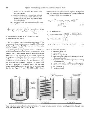
the film (see Figure 5-38 and 5-39). Oldshue (29) identi- T = tank diameter, ft
r Helical con Heat,nq co.ls also
I Heat-transfer medium act as baffles
/ Baffles
- / _....._ __ -·- ---- � - - - � .Baffles
I
II
J
-
- Heat-transfer
medium
• Jacket
(second shell)
,, Agitator
Agitator
I
I
....
........
a. Jacketed tank b. Helical coil c. Tube baffles
Figure 5-38. Heat transfer sur1aces in agitated tanks may be the actual wall of the vessel or immersed tubes. By permission, Dickey, D. S. and
Hicks, R. W., Chem. Engr., Feb. 2, 1976, p. 93 [35].