
Page 361 - APPLIED PROCESS DESIGN FOR CHEMICAL AND PETROCHEMICAL PLANTS, Volume 1, 3rd Edition
P. 361
Mixing of Liquids 329
z
H
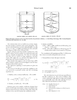
JACKETED VESSEL HITH ANCHOR-!MPELLER JACKETED VESSEL HITH HELICAL IMPELLER
Figure 5-39. Close-clearance anchor and helical impellers. By permission, Oldshue, J. Y., Fluid Mixing Technology, 1983, Chemical Engineer-
ing McGraw-Hil! Publications Co., Inc. [29].
The vertical tubes serve as baffles lo a certain extent, 3. Anchor, no baffles
but not enough to prevent some vortex formation. The (a) R,, = 300 to 4,000, coefficient is 0.38 and µ.jµ is
helical coil instaliations may have sidewall baffles (usually raised to -0.18 power.
four Yio or Yi, dia.), or baffles assembled with the coil itself. (b) R, = 30 to 300, coefficient is 1.00 and (µ,Jµ)-o.1s
(See Figures 5-23H, 5-231, 5-38 and 5-39.) and Reynolds number term is raised to 0.50 power.
Figure 5-40 gives the heat transfer relations for a flat
paddle turbine and for anchors in a jacketed vessel and The correlations of Cummings and West [5, 29] for tur-
also in coil-lank arrangements. The data of Cummings bine mixers in vessels wi.thjackets and coils are:
and West [5] are based on large equipment and give
results 16% higher for the coil and 11 % higher for the l. Vertical Helical Coils, Multiple Coils [29]
jacket than the results of Chilton, et al. [3].
Heat transfer data appear Lo be no better than ±20%
when trying to compare several investigators and the basic
fundamentals of their systems.
The exponents applying to each system are given on
the figure.
The work of Uhl [22] gave particular emphasis to vis-
cous materials in jacketed vessels, and the correlating m = can vary from 0.1 to 1.0
equations are: m = 0.1 (µ 8.621 X 10- 5)-021
1. Paddles, with or without baffles; R, = 20 to 4,000 The tube diameter, d., and tube spacing influence
the film coefficient, h., The work of Oldshue [29]
Jo
2
hT _ _ D Np J 0.57 ( cµ . 3·3 ( µw J-o 2-1 covers a practical range about as large and as small
- -0.4b ( -- - - (5- 73) as is industrially used. The tube spacing of 2 to 4
k. µ k µ
tube diameters produced consistent results.
2. Turbine, no baffles; Re = 20 to 200 where D = impeller diameter, ft
T = tank diameter, ft
Relation same as for paddle, coefficient changes from µ = bulk viscosity
0.415 to 0.535 when the turbine is about two-thirds of the �' = wall viscosity at bulk process fluid tempera-
distance down from top to bottom of the vessel. When the ture, d,
turbine is very near the bottom the coefficient is 0.44. d, = tube diameter, ft, 0.0.