Page 362 - APPLIED PROCESS DESIGN FOR CHEMICAL AND PETROCHEMICAL PLANTS, Volume 1, 3rd Edition
P. 362

330                       Applied Process Design for Chemical  and Petrochemical  Plants
                   10,000                                                                                I
                        �  Curve   Exponent   System                                            �   I   -
                        "'"  ...
                       ...   A   ...1..  .!....   Ont and Two Turbines on  Sholl, Radial Flaw,Helical Coils, no Baffles   ./  I'
                               0.14  0.33
                           B
                       ...  c   0.14  0.33   Same as A                                         I/
                       ...   D   0.24  0.33   No Bafflts,Single  Bladt Paddle (Same  Results  with  Baffles)   �   I.,   I; �
                               0.40  0.30(appro1.)Sl1-Blode Turblne,Vertlcal Tubt1  Projecting  into Tank
                           E
                               0.24  0.33
                           F   0.18  0.33   No Baffles                             I/   r;� ..   Cummings a West, Rel. 5
                                         No  Baffles  1 Si1-Blad1  Turbine (Pitched)
                                                                                                (This  Data  about 16% -
                                                                        1111  �,\\"  i-r        Higher far Cail and  II %
                                                                         ,,,
                                                                                                Higher  for Jackels  than
                                                                               ./
                                                                      �,....
                                                                          ...... ,,.\�
               1-   1,000                                         ,.,.,,�..  \\\  "'""\�·       Rtl.j.J
                                                                            "\\'\
               -                                              �·  ,,r:.°',  .,,.\\t..,,   ...  ,  .I
                                                                        )\  \.
                                                                     �, ... ,
                                                                 \
                ;;;--.....
                                                                 ,-\°'
               :[:                                         ""   �,,y              "\\'
                                                                                   :..  ,V
               ....__...                            I;'  11  i,.. �    �;?   ,,,  ..  \�
                                                  v
                                                                          .,
                                              J/ u-    1,1;  �         ..;,\\ci!  �  � !'..pc:;:::ounlap  a Rushton,
                                                                                  Ref. 6
                                           -    -                 .....  .,,.�-...
                     100                                             .,,.r:.:;;..   -
                                                                ,r:.6',,
                                            . ""   ....      �'�
                                  I/   ��  t,t> �          ,.,  ..........
                               �v  '>id                   ��
                             .......   �� o,\         I;
                        ---- ·t2:  �   ,_\\r:.,   v  ......   I.,
                          "'"i':,'  �
                        � L"   .,!;   �   L Uhl, Rel. g_g
                        �            loll Jacketed!/
                      '9oo           I  II II             10,000           100,000           1,000,000
                                        1,000
                                                                     D2Np
                                                        Reynalds  Number  1  -/"-
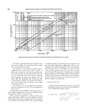
                            Figure 5-40.  Liquid mixing heat transfer.  Compiled  by permission from References 3, 5, 6, and 22.
                    The helical coil relationship was developed using   to  10,000 centipoise.  Tube spacing of coil wraps of 2  to 4
                 four vertical  baffles  of;,{,  T,  located  either  outside   tube  diameters  indicated  no  appreciable  effect  on  the
                 the coil or inside the coil  [29].               coefficient. The wider spacing gives a lower coefficient for
                    The addition of a second bank of similar coils for   materials  above  50  cp.  For  example,  the  ratio  of coeffi-
                 additional  heat  transfer  area,  either  outside  or   cients  at 4d  and 2d for water of 0.4  cp  and oil  of 50  cp
                 inside  the  first bank  of coils  will  not provide  twice   were 0.96 and 0.88 respectively.  The placement of baffles
                  the transfer of heat;  but the effectiveness is estimat-   directly  adjacent to  the wall  gives only  a  5  percent better
                 ed  to  be  70%-90%  of the  first  bank  of duplicate   coefficient than if placed  1  inch off the wall or inside the
                 coils  (assuming  the  same  heat  transfer  area  per   helical coil. However,  the power is about 10 percent lower
                 bank)  [29].  The  additional  coils  will  provide  addi-   when  the baffles are off the wall.
                  tional  baffling;  therefore,  the  need  for the  dimen-
                 sion of the vertical  baffles is reduced,  or they might   2. Vertical Tubes  [29].
                 be removed entirely.
                    The  value  of,  m,  (an  experimental  exponent)    Data  of Dunlap  and Rushton  is  given  in  [6].  This
                  [29) will run between 0.1  and 1.0 forµ ranging from   tube design can prevent the need for vertical baffles in
                 600  to 0.3 cp.                                       a tank,  and the heat transfer is good.
               The  particular work of Oldshue  and Gretton  [13]  on
             heat transfer outside  helical  coils  is  of considerable  gen-                      65(      3
             eral application.  Refer to Equation 5-74.                                     D 2        � wµ   (  �    33
                                                                       h 0  (tubes) d/k  =  0.09(  tP           r
               This is considered applicable to all sizes of tanks  using                         r r
             fi-blade  flat blade  turbines,  even  with  baffles  on  wall  or        (
             inside  single  helical  coil,  providing  that  tube  diameters            n2b  r2 (;, rl4       (5- 75)
             are  of 0.018 �  d/T �  0.036,  with viscosity  range  probably
   357   358   359   360   361   362   363   364   365   366   367