
Page 363 - APPLIED PROCESS DESIGN FOR CHEMICAL AND PETROCHEMICAL PLANTS, Volume 1, 3rd Edition
P. 363
Mixing of Liquids 331
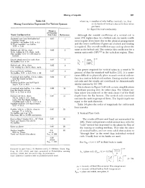
Table 5-6 where nb = number of tube baffles (vertical), i.e., four
Mixing Correlation Exponents For Various Systems or six banks of vertical tubes with three tubes
per bank
k = liquid thermal conductivity
Slope x
of Correla-
Tank Configuration tion Line Reference Although the outside coefficient of a vertical coil is
-·---------·---------- ------- ------
Jacketed cast iron hernispherica I 0.67 some 13% higher than for a helical coil, the inside coeffi-
bottom vessel cient is quite often lower due to the physical arrangement
Propeller-no baffles T /D = 2.5
U-Type impeller-no baffles. and the lower coefficient if gases are evolved and venting
T/D = !.05 is required. The over-all coefficient may end up about the
Helical coil, 9.6 in. diam. 0.62 3 same as the helical coil. The outside film coefficient for a
V2 in. tubing in 1 ft. diam. tank. system varies with (HP) 0·22 in the turbulent region. Thus
Flat paddle, T/D = 1.66 close to
bottom _
-------·--·-------·-- ------
,
Liquid depth equal to tank diam. 0.67 3
No baffles T /d = 24
---·-------------·-- ------- ------
Helical coil, 18 in. diam. 0.62 5
1 in. tubing in a 24 in. diam, tank.
------------------·-- ------- ------ The power required for vertical tubes in a vessel is 75
2 curved blade turbines. 0.67 5
No baffles. T/D = 2.5; T/d = 30 percent of that for standard wall baffles [13]. lt is some-
---·----------------- ------ ------ times difficult to physically place as much vertical coil sur-
4 vertical tube baffles, 172 in. tubes. 0.65 6
One flat blade turbine. face in a tank as helical coil surface. Dunlap studied verti-
T/D = 3 cal coils and the results are correlated for dimensionally
Turbine position one-half liquid
depth. T/d = 25.3 similar systems by [6] [29]
---------------·-- -------- ----- This is shown in Figure 5-40 with certain simplifications
4 vertical tube baffles, 1 in. tubes. 0.90 19
One flat blade turbine. to facilitate plotting with the other data. The 4-blade tur-
T/D = 3; T/d = 37.0 bine mixer was centered in the tank about Y.: of the fluid
Helical coil 34 in. diam. 0.67 13 depth from the flat bottom. The vertical coils extended
1%; in. tube in 4 ft. diam. out into the tank in groups of three. The liquid depth was
tank. One flat blade turbine,
4 baffles each 1/12 T. T/D = 3 equal to the tank diameter.
Turbine position 1/3 liquid depth. Table 5-8 gives the order of magnitude for coil-in-tank
T/D = 27.5.
heal transfer.
Paddle :4Ya in. x 2% in. close to 0.67 22
bottom. T = 14Ya in.
No baffles and 4 at Ya T. 3. Vertical Plate Coils
Oils from 100 to 46.000 centistokes
------------------- ------·--1------
Fan turbine 6 blades 12 in., 45° Pitch 0.67 22 The results of Petree and Small are summarized in
Tank and liquids like above
No baffles [29]. These coils present a solid vertical face, with the
------------------·-- -----�- ·------ "coils" vertical but impressed in the plates for flow of
Same as above 0.67 22
the heating or cooling medium. They take the place
Anchor impeller 0.5 22 of vertical baffles, and are more solid obstructions to
22V2 in. Diam. up to
Tank and liquids like above Nn. = 300 "through flow" in the vessel than individual vertical
coils. Usually four or six banks are used.
0.67
a hove
Na , = 300 For NRe < 1.4 X 10 in fluid bulk in tank:
3
I
Extracted in part from]. H. Rushton and]. Y. Oldshue, Chem. Eng. ( 2
Prog. 49, 273 (1953) and ibid., presented at Philadelphia meeting h 0 ( plate coil) (P pa.fk) = 0.1788 N: p rHB
A.I.Ch.E. (1958), Ref. 20 and 21 resp .. by permission.
Note: Reference numbers refer co published article cited. ( \ 0.33 ( ) 0.50
c pµ ; � (5 76)
-
i , j µr
� = viscosity of fluid film at mean film temperature
µ = viscosity of fluid bulk at bulk temperature
P pew = plate coil width, one plate, ft