Page 365 - APPLIED PROCESS DESIGN FOR CHEMICAL AND PETROCHEMICAL PLANTS, Volume 1, 3rd Edition
P. 365

Mixing of Liquids                                       333


                    ,5                                             3.  Determine  impeller speed:
               20
          -                 Number  on  Curve  is  Sea le
           ...
           >
          .......   �       Ratio  of Impellers, D2 /D1              N   =N   (  DI   )(2x-  l)/x            (5- 80)
                                                                               -
          Q.    10  �  ,,                                             2s    ls   0 2
                     ' �
             •      '  ' '
                     wv
           eN        ' ''
           eu;  5      \..  �  ,\                                  4.  Determine  power using x  and  compare  with  step 5
           :,-
          -'a      "2 \                                              below:
           OE             l\\
          >  Cl)          l�
           c.
          ='  2       "'
          :::, .!::!                                                                                         (5-81)
           ..  Cl)
           ••
                                        -�
           A. Cit
           ..  :;1.0       �
                                      -.
           •...J                         ...... --..
           �  0.7                         ..............   ._      5.  Determine tank volume:
          0.                                ,, ..........   ----
          -  0.5                              "�  r-,      2
           0
          -                                       �   ........   3
          .s
           a
          a:                                              4                                                 (5- 81A)
                                                     �     5
                        0.6      0.7    0.8      0.9     1.0
                      Mixing  Correlation  Exponent,  1

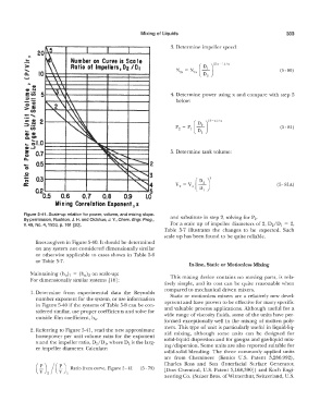
          Figure 5-41. Scale-up relation for power,  volume, and mixing slope.   and substitute in step 2,  solving for P2.
          By pennission, Rushton, J. H. and Oldshue, J. Y., Chem. Engr.  Prog.,
          V.  49,  No.  4,  1953,  p. 161  [20].                  For a scale  up  of impeller diameters  of 2,  D2/D1  =  2,
                                                                Table  5-7  illustrates  the  changes  to  be  expected.  Such
                                                                scale up has been found to be guite  reliable.
               lines as given in Figure 5-40. It should be determined
               on anv system  not considered  dimensionally similar
               or otherwise  applicable  to  cases shown  in  Table  5-6
               or Table 5-7.
                                                                          In-line, Static or Motionless Mixing
             Maintaining (h 0)  1   =  (h h on scale-up:
                                 0
             For dimensionally similar systems  [l 6]:            This  mixing  device  contains  no  moving  parts,  is  rela-
                                                                tively  simple,  and  its  cost  can  be  guite  reasonable when
                                                                compared  to mechanical driven mixers.
             1. Determine  from  experimental  data  the  Reynolds   Static  or motionless  mixers  are  a  relatively  new  devel-
               number exponent for the system, or use information
               in Figure 5-40 if the systems of Table 5-8 can be con-   opment and have proven to be effective for many specific
               sidered similar,  use proper coefficients and solve for   and valuable  process  applications.  Although  useful  for a
                                                                wide  range  of  viscosity  fluids,  some of the units have per-
               outside film coefficient,  h 0.
                                                                formed  exceptionally  well  in  the  mixing  of molten  poly-
                                                                mers.  This  type of unit is  particularly useful  in _liguid-lig-
             2.  Referring to  Figure 5-41, read  the new approximate
               horsepower per unit volume ratio for  the.exponent   uid  mixing,  although  some  units  can  be  de � 1gn_ed  � or
                                                                solid-liquid dispersion and for gas-gas and gas-h9md  mix-
               x and the impeller ratio, D2/D where D2 is the larg-
                                         1,
               er impeller diameter.  Calculate:                ing/ dispersion.  Some units are also reported sm_table f?r
                                                                solid-solid  blending.  The  three  commonly  applied  units
                                                                are  from  Chernineer  (Kenics  U.S.  Patent  3,286,992),
                        f,)   Ratio from curve,  Figure 5- 41   (5 - 79)   [Dow  Chemical,  U.S.  Patent 3,168,390])  and Koch  Engi-
               (  � )  /  (                                     Charles  Ross  and  Son  (lnterfacial  Surface  Generator,
                   2       1
                                                                neering Co.  (Sulzer Bros. ofWinterthur,  Switzerland, U.S.
   360   361   362   363   364   365   366   367   368   369   370