
Page 386 - APPLIED PROCESS DESIGN FOR CHEMICAL AND PETROCHEMICAL PLANTS, Volume 1, 3rd Edition
P. 386
354 Applied Process Design for Chemical and Petrochemical Plants
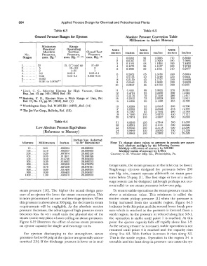
Table 6-3 Table 6-5
General Pressure Ranges for Ejectors Absolute Pressure Conversion Table
Millimeters to Inches Mercury
-
Minimum Range
Practical Operating Milli- Milli- Milli-
Absolute Suction Closed Test meters Inches meters Inches meters Inches
No. Pressures, Pressure, Pressure
Stages mm. Hg.* mm. Hg. O> < 2 > mm. Hg. < > 1 0.0394 26 1.0236 170 6.6929
2
2 0.0787 27 1.0630 180 7.0866
3 0.1181 28 1.1024 190 7.4803
1." ...... 50 75, (3") and up 37-50 4 0.1575 29 1.1417 200 7.8740
2 ......... 5 10-100 5 5 0.1969 30 1.1811 210 8.2677
3 ......... 2 1-25 1
4 ......... 0.2 0.25-3 0.05-0.1 6 0.2362 35 1.3780 220 8.6614
5 ......... 0.03 0.03-0.3 0.005-0.01 7 0.2756 40 1.5748 230 9.0551
6 ......... 0.003 8 0.3150 45 1.7717 240 9.4488
7 ......... 0.001 to 0.0005** 9 0.3543 50 1.9685 250 9.8425
10 0.3937 55 2.1653 260 10.236
* Linck, C. G., Selecting Ejectors for High Vacuum, Chem. 11 0.4331 60 2.3622 270 10.630
Eng. Jan. 13, pg. 145 ( 1958) Ref. (9) 12 0.4724 65 2.5590 280 11.024
13 0.5118 70 2.7559 290 11.417
•• Berkeley, F. D., Ejectors Have a Wide Range of Uses, Pet. 14 0.5512 75 2.9528 300 11.811
Ref. 37, No. 12, pg. 95 (1958), Ref. (1) 15 0.5906 80 3.1496 325 12.795
11 > Worthington Corp. Bul. W-205-E21 (1955), Ref. (14) 16 0.6299 85 3.3465 350 13.780
17 0.6693 90 3.5433 375 14.764
CJ> The Jet-Vac Corp., Bulletin, Ref. (15). 18 0.7087 95 3.7402 400 15.748
19 0.7480 100 3.9370 450 17.717
20 0.7874 110 4.3307 500 19.685
Table 64 21 0.8268 120 4.7244 550 21.653
22 0.8661 130 5.1181 600 23.622
Low Absolute Pressure Equivalents 23 0.9055 140 5.5118 650 25.590
5.9055
(References to Mercury) 24 0.9449 150 6.2992 700 27.559
0.9843
25
29.528
160
750
Inches Vac. Referred
Microns Millimeters Inches to 30" Barometer Note: To change above values to pressure in pounds per square
inch absolute multiply by the following factors:
10 .... 0.01 .000394 29.999606 Multiply millimeters of mercury by 0.01934-
100 .... 0.10 .003937 29.996063 Multiply inches of mercury by 0.4912
200 .... 0.20 .007874 29.992126 Courtesy C. H. Wheeler Mfg. Co., Philadelphia, Pa.
300 .... 0.30 .011811 29.988189
400 .... 0.40 .015748 29.984252
500 .... 0.50 .019685 29.980315
600 .... 0.60 .023622 29.976378 tistage units, the steam pressure at the inlet can be lower.
700 .... 0.70 .027559 29.972441
800 .... 0.80 .031496 29.968504 Single-stage ejectors designed for pressures below 200
900 .... 0.90 .035433 29.964567
1000 .... 1.00 .039370 29.960630 mm Hg. abs., cannot operate efficiently on steam pres-
- ' sures below 25 psig [1]. The first stage or two of a multi-
stage system can be designed (although perhaps not eco-
nomically) to use steam pressures below one psig.
steam pressure [ 16]. The higher the actual design pres- To ensure stable operations the steam pressure must be
sure of an ejector the lower the steam consumption. This above a minimum value. This minimum is called the
is more pronounced on one- and two-stage ejectors. When motive steam pickup pressure [l] when the pressure is
this pressure is above about 350 psig, the decrease in steam being increased from the unstable region. Figure 6-13
requirements will be negligible. As the absolute suction indicates both this point and the second lower break pres-
pressure decreases, the advantages of high pressure steam sure which is reached as the pressure is lowered from a
becomes less. In very small units the physical size of the stable region. As the pressure is reduced along line 5-3-1,
steam nozzle may place a lower ceiling on steam pressures. the operation is stable until point 1 is reached. At this
Figure 6-12 illustrates the effect of excess steam pressures point the ejector capacity falls off rapidly alone line 1-2.
on ejector capacity for single- and two-stage units. As the steam pressure is increased, stable operation is not
resumed until point 4 is reached and the capacity rises
For ejectors discharging to the atmosphere, steam along line 4-3. With further increases it rises along 3-5.
pressures below 60 psig at the ejector are generally uneco- This is the stable region. Operation in the region 3-1 is
nomical [16]. If the discharge pressure is lower as in mul- unstable and the least drop in pressure can cause the sys-