
Page 463 - APPLIED PROCESS DESIGN FOR CHEMICAL AND PETROCHEMICAL PLANTS, Volume 1, 3rd Edition
P. 463
Process Safety and Pressure-Relieving Devices 429
Solely Valve Vacuum: (a) Removal of liquid or vapor at greater rate
SV-1 +
High fl .$-• I Block than entering a vessel, capacity determined by volume dis-
Pressure� Vo Ive placed. (b) Injecting cold liquid into hot (steamed out)
t
Steam Reducing I I Driven Equipment
Station • -- (Ctntrifugal Camprmor I vessel, the condensing steam will create vacuum, and must
Pump, etc.)
Sleom Turbine be relieved. Capacity is equivalent to vapor condensed.
Driver
Safely Valve Required lo Protect Reducing Slotion Solely Valve SV-2 is Set to Protect In-breathing and Out-breathing Pum,1J In and Out: See
Discharge Pressure in Cose of Valve Failure. SV-1 Discharge Side of Turbine, as ii is
is Set at Slightly Above Downstream Pressure of Not Designed lo Withstand Inlet section on Pressure-Vacuum Relief for Low Pressure
Reducing Station, ond Protects All Equipment Steam Pressure on Exhaust Side.
Operating ot this Pressure on Sleom Header. Storage Tanks.
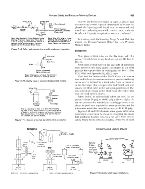
Figure 7-15. Safety valve protecting specific equipment operation.
Installation
Never place a block valve on the discharge side of a
pressure relief device of any kind, except see [I] Par. U-
135(e).
Never place a block valve on the inlet side of a pressure
relief device of any kind, unless it conforms to the code
Positive D isplacemenl practice for rupture disks or locking devices. See [1] Par.
Pump or Compressor
UG-135(e) and Appendix M, ASME code.
Sotery Valve Required to Protect Against Closed
B!ock Vo Ive Anywhere in Discharge Sys fem. Note that the intent of the ASME Code is to ensure
that under those circumstances where a pressure relieving
Figure 7-16. Safety valve in positive displacement system.
device can be isolated by a block valve from its pressure,
or its discharge, that a responsible individual lock and
unlock the block valve to the safe open position and that
this individual remain at the block valve the entire time
that the block valve is closed.
Safety (relief, or safety-relief) valves are used for set
pressures from 10 psig to 10,000 psig and even higher. At
the low pressures the sensitivity to relieving pressure is not
Oistillotion
Column always as good as is required for some processes, and for
This is Accepfoble os there is r.o Block Valve Isolating this reason most valve installations start at 15 to 20 psig.
ony Item. II Block Vo Ive Installed ot A, Sofery Valve would Figures 7-10 and 7-18 illustrate a few typical safety valve
be RE quired to Protect Condenser and Receiver. II Additional
Bloc• Valve Installed ot B, Safety Valve would be Required installations. Care must be shown in designing any mani-
for Condenser ond also for Receiver.
fold discharge headers collecting rhe vents from several
Figure 7-17. System protected by safety valve on column. valves. Sharp bends are to be avoided. Often two or more
b w ! Vent or
To Manifold 1;0 � 1 interconnected Locking Device
r<:,
Dischcrqe Hecder
Free-Opening
Covered Special
3-Way
Discharge
Plugs or
Full-open
--...
Gate Valve
Liquid
Drain
Hole
vessel
Vessel Vessel
or Pipe or Pipe
Dischorqe , A:tcrr.ote Arrongemer.ls Inlet, Alternate Arrangements Figure 7-18. Safety relief valve installations.