
Page 467 - APPLIED PROCESS DESIGN FOR CHEMICAL AND PETROCHEMICAL PLANTS, Volume 1, 3rd Edition
P. 467
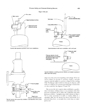
Process Safety and  Pressure-Relieving Devices                      433

                                                        Figure 7-20 cont.
                                                                                             F


                                                                     Ventplpe �


                                                                     Long-radius elbow


                                                                  Pressure
                                                                  relief--�
                                                                  valve


               Typical  pilot-operated pressure relief valve installation   Typical  pressure relief valve installation with vent pipe

                                                                                               �  Pressure relief
                                                                                                      valve

                                                                   Process laterals should
                                                                  generally not be connected
                                                                  to pressure relief valve
                                                                      piping_\
                                                                  inlet         -------------
                                                                         \--------------------

                                                                                                    Vessel


                                                                Typical  installation  avoiding process laterals connected to pressure
                                                                relief valve inlet piping


                                                                edges securely and prevent pulling and leakage.  If the sys-
                                                                tem  is  subject  to  vacuum  or  pressure  surges,  a  vacuum
                                                                support must be added to  prevent collapse  of the sealing
                                                                disk.  The flanges which hold the disk may be slip-on, weld
                                                                neck, etc. Disks to fit screwed and union-type connections
                                                                are also available.  See Figures  7-8 and 7-9.
                                             -                     The service life  of a  rupture disk is  difficult to  predict,


                                             Excess flow valve   since corrosion, cycling pressures,  temperature and other
                                                (optional)      process  conditions  can all  affect the useful  life  and cause
                                                                premature failure. A graphite-type disk is shown in Figure
                                                                7-9.  In  some  processes  it is  safer  to  replace  disks  on  a
                                              Bleed valve
                                         (may be car-sealed open)   schedule  after  the  life  factor has  been  established,  as  a
          Typical  rupture disk  assembly installed  in combination with  a pres-   planned  shut-down  is  certainly  less  costly  than  an  emer-
          sure relief valve                                     gency  one.