
Page 464 - APPLIED PROCESS DESIGN FOR CHEMICAL AND PETROCHEMICAL PLANTS, Volume 1, 3rd Edition
P. 464
430 Applied Process Design for Chemical and Petrochemical Plants
collection systems are used in order to avoid discharging requirements. Multiple valves may also be individually
a high pressure valve into the same header with a low pres- installed separately on a vessel.
sure valve. The simultaneous discharge of both valves
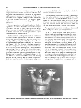
might create too great a back pressure on the Jaw pres- Figure 7-19 illustrates a newer approach at simplifying
sure valve, unless adequate arrangement has been made the dual safety relief valve installation, ASME Sect. Vlll,
in the valve design and selection. The balanced safety- Div. 1, UG-135(b) [l] and API RP-520, Part II Confor-
relief valve can overcome most of the problems of this mance [33). Note that the SRV valves are mounted on top
type system. of each of one dual vertical connections and are bubble
tight. Also see cross section view. The flow C,, valves for
Whenever possible the individual installation of valves each size device are available from the manufacturer.
is preferred, and these should be connected directly to
the vessel or pipe line [ 1, 28). If a block-type valve is con- The operational instructions of Anderson Greenwood
sidered necessary for a single valve installation, it must be & Co. for Figure 7-19 are quoted by permission:
of the full open type, and locked open with the key in The AGCO Safety Selector Valve body houses a
responsible hands, as stated earlier.
uniquely designed switching mechanism. The inter-
Dual installations are frequently made in continuous nal rotor smoothly diverts flow to either safety relief
processes, to allow switching from one valve to another valve. Conventional direct spring operated valves or
without shut down of the pressure system. A special three- pilot operated valves may be used. The inactive valve
way plug of full open type is installed directly on the ves- is totally isolated by external adjustment. To begin
sel, and the safety valves are attached to it with short pip- switchover, the retraction bushing is rotated to its
ing (Figure 7-18). The three-way valve insures that one stop. This separates the isolation disk from the stand-
side of the safety valve pair is always connected to the ves- by valve channel and temporarily "floats" it in the
sel, as this pattern valve does not have a blind point dur- main valve cavity. The index shaft is then rotated
ing switching (Also, see Figure 7-19). One of the impor- 180° to the alternate channel. The retraction bush-
tant justifications for this dual arrangement is that ing is then returned to its original position, securely
safety-relief valves may leak on reseating after discharging. seating the isolation disk beneath the valve taken out
This leak may be caused by a solid particle lodged on the of service. A red pointer indicates which valve is in
seat. This valve can be removed for repair and cleaning service and double padlocking provisions allow the
after the process has been switched to the second valve. safety selector valve to be locked in either safety relief
Each valve must be capable of relieving the full process valve position. The padlocks or car seals can only be
Figure 7-19. Safety selector valve for dual safety relief valve installation with switching. By permission, Anderson, Greenwood and Co.© AGGO.