
Page 466 - APPLIED PROCESS DESIGN FOR CHEMICAL AND PETROCHEMICAL PLANTS, Volume 1, 3rd Edition
P. 466
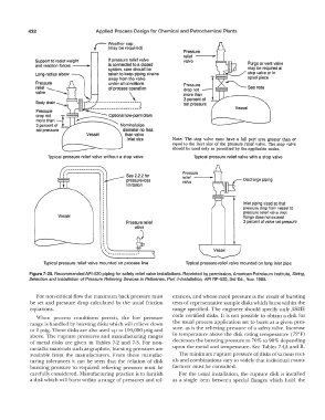
432                      Applied  Process Design for Chemical and Petrochemical  Plants
                                    r
                                          Weather cap
                                          (may be required)
                                                                      Pressure
                                                                      relief
              Support to resist weight    If pressure relief valve    valve
              and reaction forces  ---·,   is connected to a closed
                                          system, care should be
                                          taken to keep piping strains
                                          away from the valve
                                          under all conditions        Pressure
                                          of process operation        drop not
                                                  \                   more than
                                                                      3 percent of
                                      ----------      ,  I            set pressure
                                   ---------------------V                                 Vessel
               Pressure       � nal
               drop not                         low-point drain
               more than
               3 percent of                   Nominal pipe
               set pressure                    diameter no less
                                  Vessel        than valve
                                                 Inlet size       Note:  The  stop  valve  must  have  a  full  port  area  greater  than  or
                                                                  equal  to the inlet size  of the  pressure  relief valve.  The  stop valve
                                                                  should be used only as permitted by the applicable codes.
                   Typical  pressure relief valve without a stop valve    Typical  pressure relief valve with a stop valve


                         :  ,  ,--------------,  '  l   See 2.2.2 for   Pressure
                                        ,�  pressure-loss             relief                 Discharge piping
                                                                      valve
                                                 limitation

                                                                                             Inlet piping sized so that
                                                                                             pressure drop from vessel to
                                                                                             pressure relief valve inlet
                       Vessel                                                                flange does not exceed
                                                                                             3 percent of valve set pressure
                                        .
                                        I
                                        I
                                        I
                                        I
                                         '
                                         '  .......   1
                 Typical  pressure  relief valve mounted on  process line   Typical  pressure relief valve mounted on  long inlet pipe
            Figure 7-20.  Recommended APl-520 piping for safety relief valve installations.  Reprinted by permission, American Petroleum Institute, Sizing,
            Selection and Installation of  Pressure Relieving Devices in Refineries,  Part II-Installation,  API  RP-520, 3rd  Ed.,  Nov.  1988.


               For non-critical flow the maximum back pressure must   erances, and whose rated pressure is the result of  bursting
            be  set and  pressure  drop  calculated by  the  usual  friction   tests of  representative sample disks which burst within the
            equations.                                            range  specified.  The  engineer should specify only ASME
                                                                  code certified disks.  It is not possible  to obtain a disk for
               When  process  conditions  permit,  the  low  pressure
            range is handled by bursting disks which will relieve down   the usual  process  application set to  burst at a  given  pres-
            to 2  psig.  These disks are also used up to  100,000 psig and   sure, as is the relieving pressure of a  safety valve. Increase
            above.  The  rupture  pressures  and manufacturing ranges   in temperature above  the disk rating temperature  (72°:F)
            of metal  disks  are  given  in  Tables  7-2  and  7-3.  For non-   decreases the bursting pressure to 70% to 90% depending
            metallic materials such as graphite,  bursting pressures are   upon the metal  and temperature.  See Tables 7-4A and B.
            available  from  the  manufacturers.  From  these  manufac-   The minimum rupture pressure of  disks of  various met-
            turing  tolerances  it can  be  seen  that the  relation  of disk   als and combinations vary so widely that individual manu-
            bursting  pressure  to  required  relieving pressure  must  be   facturer must be consulted.
            carefully considered.  Manufacturing practice is to furnish   For the usual  installation,  the  rupture  disk is installed
            a disk which will burst within a range of pressures and tol-   as  a  single  item  between  special  flanges  which  hold  the