
Page 465 - APPLIED PROCESS DESIGN FOR CHEMICAL AND PETROCHEMICAL PLANTS, Volume 1, 3rd Edition
P. 465
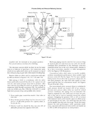
Process Safety and  Pressure-Relieving  Devices                      431

                                       Retraction  Bushing   Index Shaft


                                                                                          Lessthan3%
                          Connection and                                                  pressure loss
                          Bleed Port for                                                   at rated flow
                          standbySRV

                                Spare


                           Isolation  Disc
                           (Soft Seated)

                                     (By others)
                                                        Figure 7-19 cont.


             installed  with  the  internals  in  the  proper  position.   Discharge  piping  must be  sized for low  pressure  drop
             No special  tools are necessary for switching.      at maximum flow not only from any one valve, but for the
                                                                 combined  flow  possibilities  in  the  discharge  collection
             The alternate  concept which has  been  in use  for many   manifold all  the way  to  the vent release  point,  whether it
           years  is  to  fabricate  or  purchase  a  Tee  connection  upon   be  a  Oare,  incinerator,  absorber  or  other  arrangement
           which the two safety relief  valves can be mounted on top of   [ 13). See Figures 7-20 illustrations.
           their full-port plug or gate valve with required locking lugs.   Conventional  safety  relief valves,  as  usually  installed,
             Rupture  disks are often used  in conjunction with safe-   produce  unsatisfactory  performance when variable  back
           ty valves as shown in Figures  7-10, 7-l l, 7-12, and 7-18.   pressure exists  [10, 33). See Figure 7-6. The same variable
                                                                 back pressure forces affect the set pressure release also. At
             Inlet  piping  is  held  to  a  minimum,  with  the  safety   low  back  pressures,  the  valve  flow  falls  rapidly  as  com-
           device preferably mounted directly on the equipment and   pared with  the flow for a  theoretical  nozzle.  See  Figures
           with  the  total system  pressure  drop  loss  to  pressure  relief   19 and 20 in Ref.  [33a].
           valve inlet not exceeding 3% of the set pressure in psig,  of   For conventional  valves,  pressure drop or variations in
           maximum relief flowing  conditions  [JO]. To  conform  to   back  pressure  should  not  exceed  10%  of set  pressure.
           code (see ASME code, Sect, VIII, Div.  l-UG-127 [l]) avoid   Because  most  process  safety  valves  are  sized  for  critical
           high inlet pressure drop and possible valve chatter:
                                                                 pressure  conditions,  the  piping  must  accommodate  the
                                                                 capacity  required  for valve  relief and  not  have  the  pres-
             1. Never  make  pipe  connection  smaller  than  valve  or   sure  at the  end  of vent or  manifold  exceed  the  critical
               disk inlet                                        pressure.  Designing  for pressure  30%  to  40%  of critical
                                                                 with balanced valves,  yields smaller pipes yet allows  prop-
             2.  Keep friction  pressure drop very low,  not over I  to 2   er functioning  of the valve.  The  discharge  line size  must
               percent of allowable  pressure  for capacity  relief [l,   not be smaller than the valve discharge.  Check the manu-
                10, 25, 28,  33].
                                                                 facturer  for valve  performance  under  particular  condi-
             3. Velocity  head  loss  should  be  low,  not  over  2%  of   tions,  especially with balanced valves which can handle up
               allowable pressure for capacity relief [25].      to 70%  to 80%  of set pressure as  back pressure.