
Page 520 - APPLIED PROCESS DESIGN FOR CHEMICAL AND PETROCHEMICAL PLANTS, Volume 1, 3rd Edition
P. 520
486 Applied Process Design for Chemical and Petrochemical Plants
�) �)
R
M'
I
(c) (d) I
REGION OF
/ M
�- SUPERSONIC
·"
FLOW
M"
FORMATION 0:
VORTICES M'
VORTEX GROWTH
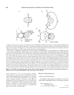
Figure 7-44 shows the sequence of events involved in diffraction of a blast wave about a circular cylinder (Bishop and
Rowe 1967). In these figures the shock fronts are shown as thick lines and their direction of movement by arrows nor-
mal to the shock front. In Figure l. l 3a, the incident shock I and reflected shock Rare joined to the cylinder surface by
a Mach stem M. R is now much weaker and is omitted in succeeding figures.
In this shock configuration a slipstream S has been formed. This slipstream is a line dividing flows of differing densi-
ties but of the same pressure. When a Mach stem is formed on a plane surface, the slipstream extends upstream, slant-
ing down to meet the surface. In the present case, however, the increased flow near the cylinder surface has caused the
foot of the slipstream to move nearer to the foot of M. The slipstream therefore presents a curved appearance. In Fig-
ure l. l 3c the feet of the Mach stems have passed though each other and are moving on a second circuit of the cylinder.
The slipstreams have been swept nearer the rear of the cylinder and intersect with the diffracted parts of the Mach stems
x and y. The commencement of two vortices is indicated at V 1 and V 2. These are probably induced by the back pressure
behind the shocks x and y interacting with the boundary layer flow at the surface of the cylinder. The shaded portion is
due to a localized region of supersonic flow. In Figure l.13d the Mach stems Mand M' have moved some way down-
stream of the cylinder. A Mach stem M" joins the free-air parts of these Mach stems with the diffracted parts Pn and P' D,
which terminate on the cylinder surface. The growth of the vortices is apparent in this figure. In Figure l. l 4a-b, the foot
of Pn has moved further around the cylinder upstream. Notice that the point of flow separation has followed this shock.
Figure 7-44. Interaction of a shock wave with a cylinder. (Source, Bishop and Rowe, 1967). By permission, Wilfred Baker Engineering, Inc.,
Explosions in Ak, 2nd printing (1983), Wilfred E. Baker, San Antonio, Texas, USA [42].
mixture between 6 and 11.5 vol percent methane. Mixtures of Flammable Gases
These limits are known as limits of ignitibility, indicat-
ing the igniting ability of the energy source. Limit mix- Composite Flammability Mixtures
tures that are essentially independent of the ignition
source strength and give a measure of the flame to Le Chateliers Rule allows the calculation of the lower
propagate away from the ignition source are defined as flammability (explosibility) limits for flammable mixtures:
limits of flammability [ 43]. Considerably more spark
energy is required to establish limits of flammability, Mixture composite LEL =
and more energy is usually required to establish the 100 volume/volume
upper rather than the lower limit. (7- 54)
(text continued an page 491)